| PFTrack Documentation | Node Reference |
Camera Solver
Overview | Preparing the shot | Setting camera parameters | Lens distortion correction | Trackers | Solving for camera motion |Residual errors | Coverage | Editing and refining the solve | Tracker adjustment | Tracking difficult shots |
Solving multiple cameras | Using Helper Frames | Tracker Constraints | Display controls | The Solver log
Overview
The Camera Solver node can be used to estimate camera motion using a set of feature tracks generated by one or more Auto Track or User Track nodes.
The Camera Solver node can have multiple inputs and multiple outputs, and it can solve for more than one camera at the same time provided the set of trackers have been tracked in each input clip. Helper frames can also be used to assist with estimating tracker positions.
Constraints on tracker positions can be defined, ensuring a set of tracker lies exist at the same point in 3D space, or lie a flat plane or a straight line, and lens distortion can be corrected for automatically.
The camera solving process can be influenced by the user in many ways, such as specifying a pair of initial frames to start from, specifying approximate feature distances from the camera, or even providing a hint to how the camera is moving. Error graphs are available to assess which features are not being solved accurately.
Note that automatic estimation of lens distortion coefficients requires a fairly large set of trackers, distributed over as much of the image area as possible. Without this, the lens distortion coefficient might not be estimated accurately.
The Camera Solver works by examining the motion paths of tracking points and trying to work out suitable camera parameters (such as focal length) and a motion transformation that can explain the paths. Because trackers have so much influence over the Camera Solver, it is very important to use a set of good quality tracker points.
Note that the Camera Solver is only able to function using the tracking points provided to it. If those tracking points are not in the correct position, or do not provide enough parallax information to resolve the camera motion, the results generated by the solver may not be what you expect.
This can especially be true in situations where there is a low amount of parallax, or the trackers have not been well distributed over the scene. In these cases, there can sometimes be several different camera motions that "fit" the tracker positions, and the Camera Solver is unable to distinguish one from another. In these cases, further information (such an approximate tracker distances) must be provided in order to reduce the ambiguity in the motion.
Preparing the shot
The Camera Solver is able to function when four or more trackers are tracked between adjacent frames, although using more then four trackers will increase the accuracy of the solution, and will reduce the amount of error caused by noise in the tracker paths. Each tracking point should be tracked over multiple frames, and tracking points that exist over a long period are often those that provide most benefit to the solver.
For simple shots, the Auto Track node can be used to generate a set of tracking points automatically.
Alternatively, a User Track node can be used to manually create tracking points. This is often necessary in situations where there is complex camera motion, or the image data is such that automatically generated trackers do not exist for very many frames.
Parallax
In order to estimate the camera position accurately, tracking points should be placed on both foreground and background image features. This means that the parallax motion of the trackers can be used to estimate both the position of the camera and the distance from the camera to the tracking point.
There should also be an approximately even number of foreground and background trackers for the best results: Having too many trackers in one part of the scene may overwhelm the solver, decreasing the accuracy of the camera path.
Tripod-mounted shots
When tracking shots from cameras mounted on a tripod, is is often tempting to assume that the virtual camera used by PFTrack is not translating at all, and there is no parallax in the shot. In the real-world however, this is rarely the case since the tripod mount point on the camera will not correspond exactly to its optical centre.
It these situations, is often useful to first assess the amount of parallax in a shot, which can be done easily using the User Track node as follows:
1. Place a tracker on a foreground feature, and track it through as much of the clip as possible.
2. Whist keeping the tracking point selected, enable the 'Centre View' option. This will centre the Cinema viewport on the tracking point.
3. Using the left mouse button, scrub left and right through frames in the scrub bar.
By keeping the foreground tracker in a fixed location, you should be able to see how much parallax is in the shot by comparing it against the background motion.
Using large numbers of trackers
Sometimes, a better quality solve can be generated from six or more manually placed tracking points than from a set of 50 or so automatically tracked points.
The time it takes to solve for camera motion will depend on both the number of frames that require solving, and the number of trackers visible in each frame.
If a large number of trackers is required for other purposes further down the tree, it is often better to create a second tracker and camera solver node pair in which the 3D positions of the additional trackers can be generated whilst keeping the existing camera motion fixed.
Setting initial frames
The Camera Solver works by first constructing a partial solution between the initial frames. In order to get a good overall camera solve, it is important that this initial solution is fairly accurate, so the first step in tracking a problematic shot is to ensure a good initial solution can be obtained. This will then be extended outwards, adding more frames until the entire camera path is complete.
The solver can be halted once the initial solution is produced, making it easier to see if the starting point for the whole solution is accurate. Tools are provided to manually extend a solution outwards by one frame at a time, meaning small adjustments can be made manually to either the camera path (via the curve-editor) or the trackers (by adjusting their distance from the camera) whilst the solution is being completed.
For clips shot with a zoom lens, a good initial solution is more likely to be found if the initial frames are placed in part of the shot which is not zooming, if at all possible.
If your clip contains different types of camera motion (for example, only one section of the clip contains camera translation, and the remaining motion is rotation only), make sure to set the initial frames in part of the clip that exhibits as much parallax as possible between the foreground and background tracking points.
Avoid setting initial frames in parts of the shot that have very little parallax as this can adversely affect the rest of the solve.
Setting camera parameters
The most important parameter that can be set before motion is solved is the camera focal length.
Note that entering a focal length value is a physical unit such as millimetres should only be done when the camera Sensor size is known. These two values are used together to calculate a field of view for the camera. If the sensor size is not accurate, the field of view will not be correct, and this may adversely affect the accuracy of the camera solve.
In order to change the sensor size of the camera, the value must be updated in the Clip Input node at the top of the tree where the clip parameters are defined.
Camera controls
The Camera tab contains information about the camera associated with the current clip. If more than one input clip is present, the current camera (and clip) can be changed using the Current clip menu option.
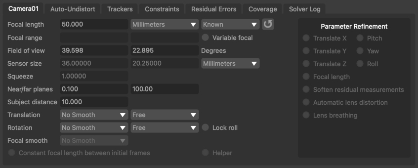
Focal length: Displays the camera focal length at the current frame. Focal length can be set as Known, Unknown or Initialised. If the focal length of the camera is known beforehand, entering the value here can often improve both the speed and accuracy of the camera solver. Setting focal length to Initialised will allow a minimum and maximum value to be specified in the focal range edit boxes. For cameras with a constant focal length, setting focal length to Initialised will also allow an initial value to be entered into the focal length edit box. Note that in order to enter a focal length measured in any unit other than Pixels requires that the camera sensor width and height is set correctly.
R: If an input camera focal length was available up-stream, clicking this button will reset the current focal length to this value. This can be useful in situations where the input focal length is used as a hint to the camera solver.
Focal range: When focal length is set to Initialised, these edit boxes define the minimum and maximum allowable values of focal length.
Variable focal: Allow the camera focal length to vary throughout the clip. If focal length is set to Initialised, the minimum and maximum values over which focal length can vary may be entered into the Focal range edit boxes.
Field of view: The horizontal and vertical field of view at the current frame, measured in Degrees.
Sensor size: The horizontal and vertical sensor size. The sensor size can be changed in the Clip Input node.
Squeeze: The current lens squeeze ratio, which can be changed in the Clip Input node.
Helper: This checkbox indicates that a set of photos attached to the secondary input will be used as helpers to assist in the main camera solve.
Motion hints and constraints
The Translation and Rotation menus can be used to specify various hints and constraints for how the camera is moving. The first menu is used to control the amount of smoothing that is applied to either the translation or rotation components of motion. Smoothing options are None, Low, Medium and High.
The second menu can be used to specify either a constraint on the motion (for example, 'No Translation'), or indicate that a hint should be used. Translation constraints are as follows:
- No Translation: the camera is not translation at all, and there is no parallax in the shot at all. Note that this option is rarely used, since it refers to the position of the camera's optical centre. Even when mounted on a tripod, the camera will still be translating slightly, since the centre of rotation (the tripod mount point) will not correspond exactly to the camera's optical centre.
- Free: A freely moving camera
- Off-Centre: A camera that is mounted on a tripod, rotating around a point slightly offset from the true optical centre
- Small: A camera that translates a small distance compared to the distance from the camera to the tracking points
- Linear: Restrict camera motion to a straight line
- Planar: Restrict camera motion to a flat plane
- Metadata hint: When available, use metadata in the source media to provide a hint to camera translation
- Upstream hint: Use the upstream camera translation as a hint (for example, generated manually using the Edit Camera node).
Rotation constraints are similar, but are limited to No Rotation, Free, Metadata hint and Upstream hint.
Lock roll: Lock the camera roll (i.e. rotation around the Z axis). This can often increase the quality of the camera solve in situations where the camera is only rotating around the X (pitch) and Y (yaw) axes.
Focal smooth: Specify how smooth the camera focal length changes are for cameras with a variable focal length. Options are None, Low, Medium and High.
Constant focal length between initial frames: In situations where the camera focal length is varying in only part of the shot, a better quality solution can often be obtained if the initial frames are positioned such that the focal length is constant between those frames. If this can be done, enabling this option will mean the camera solver is more likely to find a good quality initial solution.
Lens distortion correction
In order to get the most accurate estimate of camera motion and tracker positions, it is important to account for any lens distortion present in the images. This can be done in several ways:
- Pre-correcting lens distortion the clip using the Clip Input node
- Shooting calibration grids and building a distortion preset using the Movie Camera Preset editor
- Using Auto-undistort and specify approximate bounds on the distortion coefficient.
Auto-undistort
When the camera is set to use automatic lens distortion correction in the Clip Input node, you can indicate roughly how much distortion is present in the clip using the Range option and enable automatic undistort using the Estimate check-box.
The Range can be set to either Minimal, Moderate, Significant or Custom, where Minimal corresponds to a very small amount of distortion, and Significant corresponds to a much wider-angle lens.
Lower and upper bounds on the distortion coefficient are provided next to the Range control, and these can be edited manually when in Custom mode.
After solving the camera, the image in the Cinema window will autmatically adjust in size to represent the full undistorted image. If desired, the size of the image can be fixed to match the original image by enabling the Crop to input image size option before solving. This can have an effect on how ST-Maps are exported. Further details are available in the Scene Export node.
After solving, the actual distortion value calculated for the current frame is displayed to the right:
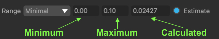
Range: This menu can be used to define the distortion range: Minimal, Moderate, Significant or Custom, where Minimal corresponds to a very small amount of distortion, and Significant corresponds to a much wider-angle lens. The lower and upper bounds on the distortion coefficient are provided next to the Range control, and these can be edited manually when in Custom mode. The actual distortion value found during the solve is displayed to the right next to the Solve control.
Estimate: Enabling this option means the camera solver will attempt to estimate a suitable lens distortion coefficient during the camera solve.
Account for lens breathing: When enabled, the camera solver will attempt to automatically correct for additional motion in the image that occurs when focus changes also affect the camera field-of-view.
Crop to original image size: When undistorting the image after solving, the original image size will be maintained.
Note: if you aren't sure what distortion range to use, try guessing first, solving your camera and then look at the calculated distortion value. If it's at the maximum of your range this means PFTrack tried to increase it more but couldn't. In this case, adjust the Range control upwards by one setting to increase the maximum allowable value, solve again, and see if that gives better results.
For example, if you set the Range to Moderate (0.1 to 0.2) and then solve your shot and the final distortion estimate is 0.2, try changing the Range to Significant and solving again to see if this gives a better result. You can always undo afterwards if the result isn't any better.
Trackers
The trackers list contains information about all trackers being used to solve for camera motion.
![]()
Name: The tracker name.
Active: Indicates whether the tracker is active in the solve or not.
Hard: Indicates whether the tracker path should be considered as a hard or soft constraint on camera motion. By default, automatically generated trackers (from an Auto Track node) are defined as soft constraints, and manually placed trackers (from a User Track node) are defined as hard constraints. The camera solver assumes that the path provided by a tracker marked as a hard constraint does not contain errors. Trackers that are marked as soft constraints may have small errors in their tracker paths without affecting the overall camera motion.
Weight: The weight given to a particular tracker in the solution. The default value is 1.0. A higher value will mean the camera solver expends more effort to match a 3D tracker position to its path, possibly at the cost of decreased accuracy elsewhere. Changing the tracker weight can often help to lock a solution down onto a particular tracker.
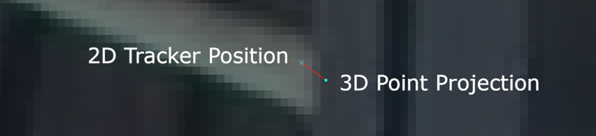
Residual: The residual error (measured in pixels) for the tracker in the current frame. The residual error (or reprojection error) is the difference between the tracker path position and the projection of the 3D tracker point onto the camera plane. Ideally, the residual error should be close to zero for each tracker.
Distance: The distance from the current camera frame to the tracker's 3D position in space.
Frame: The frame number in which the tracker distance has been initialised.
Initialised: The distance to which the tracker has been initialised in the frame.
Uncertainty: The uncertainty in the initialised tracker distance.
Tracker controls
All/None: Select all or none of the trackers from the list.
Activate: Activate all selected trackers in the camera solver. Active trackers will contribute to the solution. Trackers can also be activated individually by ticking the Active column in the tracker list.
Deactivate: Deactivate all selected trackers in the camera solver. Inactive trackers will not contribute to the solution. Trackers can be deactivated individually by un-ticking the Active column in the tracker list.
Weights: Display a popup window allowing the weight for all selected trackers to be set at the same time.
Distances: Display a popup window allowing the initialised distance and uncertainty for all selected trackers to be set at the same time.
Hard: Change all selected trackers to hard constraints. Trackers that are marked as hard constraints are assumed to have accurate tracker paths that do not contain any errors. Trackers can also be set to hard constraints individually by ticking the Hard column in the tracker list.
Soft: Change all selected trackers to soft constraints. Trackers that are marked as soft constraints may have small errors in their tracker paths without affecting the overall camera motion. Trackers can also be set to soft constraints individually by un-ticking the Hard column in the tracker list.
Push/Pull: When enabled, initialised tracker distances and uncertainties can be set interactively in a Viewer window. Click and drag with the left mouse button to adjust the Initialised tracker distance, or hold the Ctrl key whilst dragging to adjust the tracker Uncertainty. Hold the Shift key to adjust the actual tracker distance.
Adjust: Click the Adjust button to make adjustments to selected trackers. Further information is available in the Tracker Adjustment section.
Min/max tracker distance: For trackers that do not have an initial distance and uncertainty, a minimum and maximum distance can be entered here to assist the camera solver. This can be useful in situations where the camera is viewing a scene that is bounded (for example, by walls) and an approximate distance from the camera to the boundary is known.
Orientation controls
Once the camera is solved, it can quickly be oriented using the buttons and menus at the bottom of the Trackers tab:
Set Origin: Click the Set Origin button to translate the entire scene so the ground-plane origin is at the average 3D position of all selected trackers.
Set Axis: When two trackers are selected, Click the Set Axis button to re-orient the ground-plane so an axis direction matches the tracker positions.
Set Plane: When three or more trackers are selected, click the Set Plane button to fit an axis plane to the tracker positions. PFTrack uses a Y-up coordinate system.
Alternately, the Orient Camera node can be used, which provides a richer toolset. PFTrack uses a Y-up coordinate system, so the ground plane corresponds to the X-Z plane.
Solving for camera motion
Click the Solve All button to use the 2D tracker locations to solve for camera motion and 3D tracker positions. Several controls are available that adjust how the camera is solved, and additional tips are available in the Trackling difficult shots sections.
Tracker Groups
All the trackers generated by tracking node such as Auto Track or User Track will be placed into a single Tracker Group for each node and passed downstream into the Camera Solver. The Tracker Groups control should be used to select which tracker groups to use to solve for camera motion. By default, all input groups are enabled.
If you wish to rename the tracker groups, this should be done by renaming the node in the Workpage.
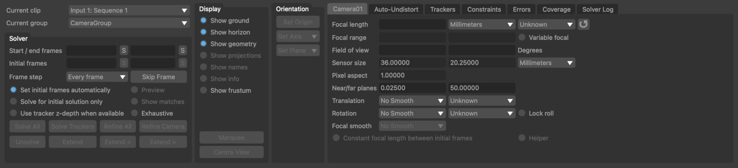
Solver controls
Current clip: The clip that is being displayed in the Cinema window. The Camera control tab will display information for the camera associated with the current clip.
Tracker groups: The tracker groups that will be used to solve for camera motion. Each upstream node used to generate trackers will provide a single group, and these can be enabled or disabled as required when solving.
Start/end frames: Start and end frames to use for the camera solve. Click the Store button to set the current frame number as either the start or end frame.
Initial frames: The pair of frames to use to construct the initial solution. Click the Store button to set the current frame number as either the first or second initial frame. Either one or two initial keyframes can be specified manually. If only one is specified, the other is estimated automatically.
Frame Step: This menu can be used to speed up the solving process for very long shots by only solving for a sub-set of the total number of frames at first and then adding the missing frames once the partial solution is complete. Options are Every Frame to solve for every frame in the clip (the default), Every 2 Frames, Every 5 Frames and Every 10 Frames to solve for one frame every 2, 5 or 10 frames in the clip.
Skip Frame: Skip the current frame during the camera solve. Once skipped, the button label will change to Un-Skip Frame to include the frame in the solve. When a frame is skipped, the camera motion will not be updated, and will instead be interpolated from nearby frames. Skipping frames can be useful when one frame is missing or corrupted due to some sort of image degradation.
Set initial frames automatically: When enabled, the initial frames will be set automatically by searching for a span of frames that contains enough trackers to solve for camera motion.
Solve for initial solution only: When enabled, the camera solve will stop once the initial solution has been generated. The initial solution is camera motion and tracker positions for all frames between the two initial frames.
Use tracker z-depth when available: This option is available if the input clip has a z-channel available, containing z-depth values at each pixel. Features tracked throughout such a clip will have a z-depth value associated with each track position, and the Camera Solver node can make use of this information to increase the accuracy and robustness of the camera solve. See the documentation for the Attach Z-Channel node for further information.
Initial Preview: When enabled, a preview of the solution at the initial camera frames will be generated. This can be used when adjusting the initial frames to determine which values perform best.
Initial matches: When enabled, only trackers that are present in both initial frames will be displayed in the Cinema window. This can be used when adjusting the initial frames to identify situations where there are enough trackers available to generate an initial solution.
Exhaustive: When enabled, the solver will spend more time adjusting the overall solution each time a new frame is added. This can result in better quality solves, but for long clips can also increase processing time significantly.
Solve All: Solve for camera motion and tracker positions. The camera solve can be run in the background by holding the Shift key whilst clicking on the Solve All button.
Solve Trackers: Solve for 3D tracker positions only. This can be used in situations where additional trackers have been created up-stream to estimate new tracker positions without re-solving for camera motion. Hold the Shift key when clicking to solve for the 3D position of selected trackers only.
Refine All: Adjust tracker positions and camera motion to better match the tracker paths. Refinement can be run multiple times, and a longer refinement can run in the background by holding the Shift key whilst clicking on the button.
Refine Camera: Refine the current camera only, leaving trackers in their current positions. This can be useful to bring the camera into alignment with trackers after their 3D positions have been manually adjusted.
Unsolve Frame: Un-solve the camera at the current frame. This will remove the translation and rotation keyframe, causing the camera path the be linearly interpolated from nearby keyframes. After a frame has been un-solved, it can be solved again using the Extend buttons described below.
Extend: Solve for any frames between the start/end frame that are currently un-solved. This can be used to extend a partial solution outwards into more camera frames, or when footage has been replaced with a longer clip. After the solution has been extended, it is often helpful to click the Solve Trackers and Refine All buttons to make sure as many trackers as possible are solved and reduce the overall solution error.
Extend : Extend the current solution by one frame towards the start of the clip. After the solution has been extended, it is often helpful to click the Solve Trackers and Refine All buttons to make sure as many trackers as possible are solved and reduce the overall solution error.
Extend >: Extend the current solution by one frame towards the end of the clip. After the solution has been extended, it is often helpful to click the Solve Trackers and Refine All buttons to make sure as many trackers as possible are solved and reduce the overall solution error.
Residual Errors
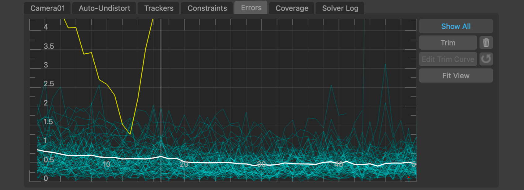
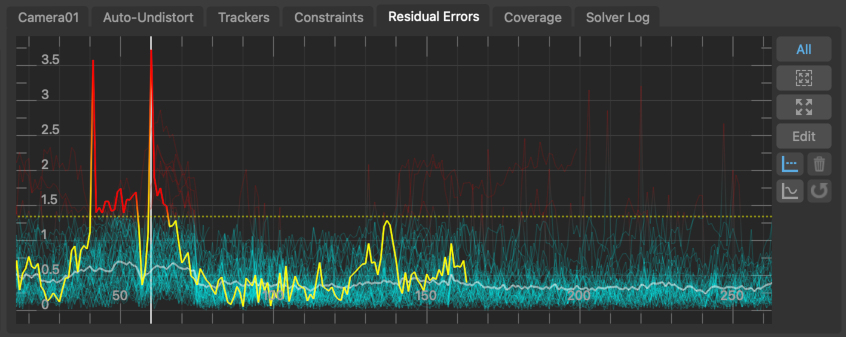
The errors graph plots the Residual Error in pixels (also called the reprojection error) for each tracker in each frame, along with the average residual error for all trackers visible in a frame. Selected trackers are shown in yellow, and unselected trackers are shown in light blue. The average residual error graph is shown in white. The error graph can be translated and scaled by clicking and dragging with the right or middle mouse buttons.
The residual error is the difference between the 2D tracker path position and the projection of the 3D tracker point onto the camera plane. Ideally, the residual error should be close to zero for each tracker:
A tracker may have a large residual error for several reasons:
1. If a tracker is marked as a Hard constraint and has a large residual error in most frames, it often means that the tracker path does not correspond to a fixed point in 3D space.
This can be caused by a tracker being positioned over a "virtual corner" (i.e. an image feature that looks like a corner in the image, but is formed by the intersection of edges in the scene at different distances from the camera. As the camera moves, the apparent intersection of the edges changes). In these cases, the tracker should probably be de-activated.
2. If a tracker is marked as a Hard constraint, and is tracked accurately but has a residual error that increases significantly in certain frames, it often indicates that the camera position in those frames is incorrect.
Adding more trackers to the solution, or providing estimates of tracker distances or camera focal length can often help out here.
3. Trackers that are marked as Soft constraints may also have an small overall error that increases significantly in certain frames. This can often be caused by the tracker jumping onto a different image feature in those frames.
These frames do not influence the overall average error by much because of the soft constraint, and these jumps can be removed by trimming the error graph.
Residual Error Controls
Click and drag right mouse button in error graph to pan the graph. Click and drag middle mouse button in error graph to zoom the graph (or use the mouse wheel, holding Alt/Option to zoom vertically instead of horizontally).
All: When enabled, error graphs will be shown for all trackers, otherwise graph will only be shown for selected trackers.
 : Click the Fit Area button and drag with the left mouse button in the graph to draw a rectangle, and fit the graph viewpoint to that area.
 : Click the Fit View button to scale and translate the error graph so all tracker error lines are visible.
Adjust: Adjust the selected tracker in the Cinema window using the Tracker Adjustment tools.
Trimming trackers
 : Click the Trim button to display a trim line, allowing all trackers whose residual errors are larger than a particular value to be hidden in those frames and ignored during the camera solve or refinement.
The trim line can be moved up and down by dragging it with the left mouse button. Once activated, trimming will remain active even if the Trim button is disabled - the Trim button only controls whether the trim line is displayed or not; not whether trimming itself is active. To delete the trim click the Delete Trim  button (only available when the trim line is not displayed).
If a tracker is trimmed in a particular frame it will remain hidden in that frame until the trim line is changed or deleted.
 : Click the Trim Curve button to toggle between moving the trim line as a whole and editing the shape of the trim line to allow more flexible trimming where a single value for the entire sequence is not sufficient. The trim line can be edited using the standard controls for manipulating a Bezier curve.
 : Click the Trim Reset button reset the shape of the trim line.
Coverage
The Coverage Panel displays information about the frames in which each tracking point has been tracked. This can be used to evaluate how well tracking points are distributed throughout the clip, which will help to provide an accurate camera solve without any jumps in the camera path.
Coverage keys display
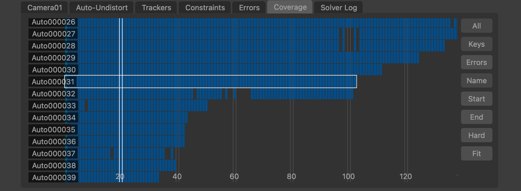
By default, the Coverage Panel displayed keyframe information showing how tracking points have been positioned and tracked. Each frame in which the tracker is present is shown with a blue square. Light-blue squares indicate where automatically generated tracking points were initially placed, and yellow squares show frames in which manually generated tracking points were keyframed. Frames in which the tracker is visible but has not been positioned are displayed in dark red. It is important to ensure that tracking points have been positioned in all frames in which they are visible, as this can significantly affect the accuracy of the camera solve.
Coverage error display
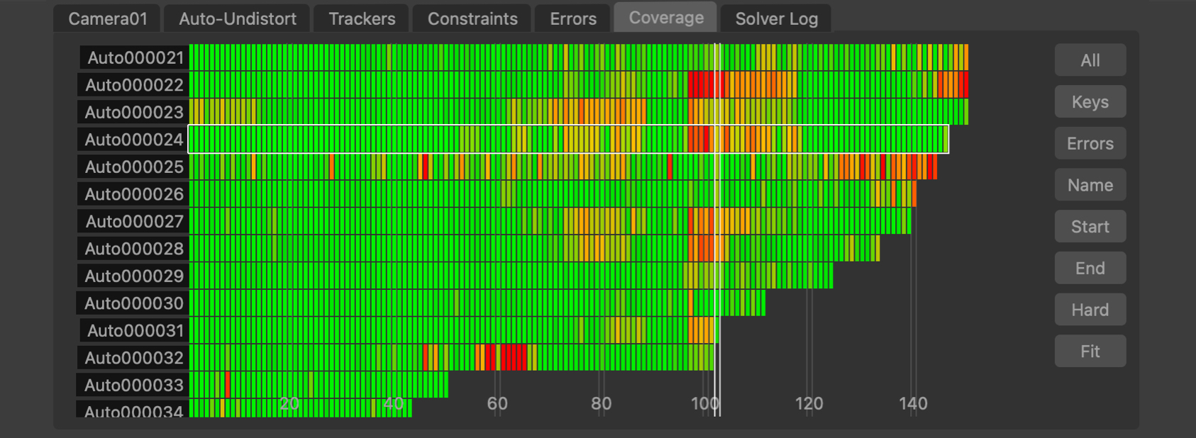
Alternatively, the Coverage Panel can also display the residual error for each tracker by clicking the Errors button. This switches the colour-coding of each indicator to show the error of the solved tracking point in each frame. This is colour-coded to show green for less than 0.5 pixels error, yellow for less than 1.5 pixels and red is greater than 2.5 pixels.
Coverage panel controls
The Coverage Panel can be panned horizontally or vertically by clicking and dragging with the right mouse button. Clicking and dragging with the middle mouse button will zoom either horizontally or vertically to increase the number of tracking points and frames that are displayed in the panel.
The mouse wheel can also be used to zoom horizontally, or vertically if the Alt/Option key is held.
Clicking on an indicator with the left mouse button will select the tracking point and display that frame in the Cinema window. Holding the Ctrl key will allow multiple tracking points to be selected.
Double-clicking on an indicator with the left mouse button will select the tracking point and immediately switch to display the node which generated that tracking point. This can be used to quickly jump to a User Track node to manually adjust a tracking point to correct a tracking error.
All: Switch between displaying all trackers, or only those trackers visible in the current frame.
Keys: Display keyframe information, showing where targets have been tracked and manually positioned.
Errors: Display residual error information.
Name: Sort the tracking points by name, in alphabetical order.
Start: Sort the tracking points according to the first frame in which they are tracked.
End: Sort the tracking points according to the last frame in which they are tracked.
Hard: When both Hard and Soft constraint trackers are present, this button can be used to switch between displaying all trackers, or only those marked as a Hard constraint.
Adjust: After selecting a tracker, click the Adjust button to adjust the tracker position directly in the Cinema window using the Tracker Adjustment tools.
 : Click the Fit button to fit the tracker points to the coverage window. This will zoom in or out as necessary, displaying as many tracking points and frames as will fit in the viewport.
Editing and refining the solve
After the camera motion has been solved, the 3D path and tracker positions can be viewed in the Viewer windows.
Trackers are also shown in the Cinema window coloured according to how well their projected position matches their 2D tracker locations.
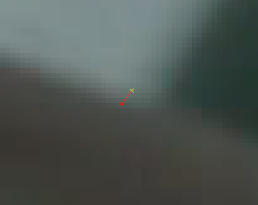
Trackers that match their 2D location well (with a residual error less than 1 pixel) are coloured green, trackers with residual errors less than 2 pixels are coloured orange, and trackers with residual errors larger than 2 pixels are coloured red.
An error line is also drawn connecting the projected tracker position with its 2D tracker location. The difference between the projected tracker position and the 2D location is referred to as the Residual Error:
The tracker list (displayed by clicking the Trackers tab) will also display the residual error and the distance of each tracker from the camera position in the current frame.
Editing trackers
The Residual Errors tab will display a graph showing the residual errors for each tracker, along with the average error for all trackers in white. Trackers can be selected from here by clicking in the graph with the left mouse button, or by clicking in the Cinema window or using the selection Marquee.
The Coverage tab displays keyframe and residual error information for each individual tracker.
Trackers with large residual errors should be examined, and deactivated or adjusted if they correspond to points that are moving different from fixed points in the scene.
For example, these might be trackers located on independently moving objects, or they may correspond to false corners that do not represent fixed points in 3D space. This is illlustrated in the following example where the intersection of two edges at different scene depths forms a high contrast point that forms a false corner. As the camera moves, the intersection these line will correspond to different 3D points in different frames:
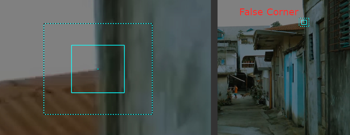
Conversely, true corners always correspond to the same 3D point in all frames.

Editing the original tracking points can be done in an upstream User Track node (which can also be used to fetch trackers from an Auto Track node for editing).
Alternatively, adjustments to the tracking points can also be made directly in the Camera Solver node using the Tracker Adjustment tools.
Refining the camera solve
Refinement is a process that starts from the current camera motion and 3D tracking points, and attempts to reduce the overall Residual Error by adjusting the camera positions and 3D point locations.
After adjusting tracker locations, the camera motion and 3D tracker points can be refined to improve the solution by clicking the Refine All button in the solver controls, or the camera motion can be refined on its own by clicking the Refine Camera button.
Individual camera parameters can be enabled or disabled as needed when refining the camera motion:
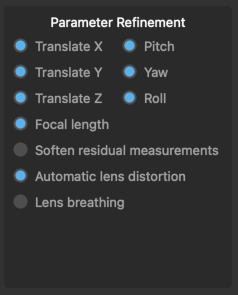
Translate X, Y, Z: These controls affect the refinement of camera translation. The X, Y and Z axes correspond to the local camera frame (i.e. X is the direction to the right, Y is the camera's up direction, and Z is the camera's viewing direction).
Pitch, Yaw, Roll: These controls affect the refinement of camera rotation, with the X, Y and Z axes corresponding to the local camera frame (i.e. rotation around the X axis is pitch, Y axis is yaw, and rotation around the Z rotation corresponds to roll).
Focal length: This allows refinement of the camera focal length if it is unknown or estimated.
Soften residual measurements: Enabling this option will make PFTrack adjust the error residual measurements during refinement to better adapt to larger tracking errors, which can help when refining camera motion for otherwise difficult shots.
Automatic lens distortion: Enabling this option will allow the automatic lens distortion parameters to be adjusted during refinement.
Lens breathing: This option can be used to control whether automatic lens breating correction is adjusted during refinement.
The camera motion and 3D tracker positions can be adjusted and refined multiple times until a satisfactory solution is obtained. If many Auto Track features are being used, other tools such as the Trim line can also be adjusted before refining the camera motion.
If all tracking points look good, but the camera motion is still incorrect after refinements, this may be an indication that other data such as the focal length or distortion parameters are wrong.
Tracker Adjustment
![]()
The tracker adjustment buttons appear in the Cinema window when a tracker is selected for editing by clicking the Adjust button. The Cinema will zoom in to centre on a closeup of the tracking point.
Whilst zoomed in, the tracker position, window, or search window can be adjusted in the Cinema using the left mouse button.
The default interaction to change the tracker position is click and drag the background image to align with the tracking point.
Alternatively, if you prefer to click and drag inside the tracking window to move to tracker whilst keeping the background image fixed, disable the move background instead of tracker option in the Cinema/Viewer preferences window.
The size of the window (or search area) can adjusted by moving an edge or corner. Hold the Ctrl key to adjust the window asymmetrically.
The Alt/Option keyboard modifier can be held to ensure only the tracker position is changed, regardless of the mouse position. This behaviour can be reversed in the User Preferences window if desired, so the modifier must be held to make any changes to the window or search area.
Note: Adjustments made to trackers using these tools will be passed downstream to other nodes, but do not affect the original tracker in upstream nodes.
Controls
The following buttons can also be used to adjust or re-track, and quickly correct any errors before refining the camera solve:
![]() : Click the Re-Solve button to re-solve the tracker position.
: Click the Re-Solve button to re-solve the tracker position.
![]() : Click the In-point button to set the tracker in-point to the current frame.
: Click the In-point button to set the tracker in-point to the current frame.
![]() : Click the Track backwards button to track backwards by 5 frames, starting from the current frame..
: Click the Track backwards button to track backwards by 5 frames, starting from the current frame..
![]() : Click the Track backwards once button to track backwards by 1 frame, starting from the current frame.
: Click the Track backwards once button to track backwards by 1 frame, starting from the current frame.
![]() : Click Hide button to hide the tracker in the current frame, or click Show to re-show it.
: Click Hide button to hide the tracker in the current frame, or click Show to re-show it.
![]() : Click the Track forwards once button to track forwards by 1 frame, starting from the current frame.
: Click the Track forwards once button to track forwards by 1 frame, starting from the current frame.
![]() : Click the Track forwards button to track forwards by 5 frames, starting from the current frame.
: Click the Track forwards button to track forwards by 5 frames, starting from the current frame.
![]() : Click the Out-point button to set the tracker out-point to the current frame.
: Click the Out-point button to set the tracker out-point to the current frame.
![]() : Click the Reset button to reset all tracker adjustments, reverting the tracker back to the original state passed into the node.
: Click the Reset button to reset all tracker adjustments, reverting the tracker back to the original state passed into the node.
Nudge keyboard shortcuts
Holding down the Alt/Option modifier key while pressing the Left Right Up Down cursor keys will nudge the tracker position 1 pixel in a direction. The distance a tracker is moved can be changed in the preferences, along with the keyboard shortcuts for each direction.
Additional keyboard shortcuts are available to provide finer-grain adjustments (Ctrl + Alt/Option) modifier keys by default). This reduces the adjustment by a scale factor (0.25 by default) which can be changed in the preferences.
Tracking difficult shots
Listed below are several steps that can be taken to influence the camera solve and refinement process, which can help when tracking difficult shots Note that there is generally no one process that can track every shot first time - tracking very difficult shots is often an incremental process where multiple techniques are necessary.
Camera and lens setup
If the shot contains a significant amount of lens distortion, make sure that is corrected before solving, or at least set bounds on the auto-undistort coefficient that are approximately correct.
Make sure the camera focal length looks sensible, and enter an approximate initialised value if necessary. In order to enter a focal length measured in a unit such as millimeters, the camera sensor/film back size must be set correctly. Entering a known focal length will make it easier to solve for camera motion, and the solver will also run at a faster speed.
Camera motion can be constrained so the camera is not translating, or is only moving in a certain path such as along a straight line or a flat plane.
Tracker distribution
Make sure the trackers are well distributed over the image frame, and in both the foreground and background of the shot, and make sure there are not too many poor quality Auto Tracks. For difficult shots it is generally recommended to use the User Track node and ensure all tracking points are tracked accurately and well distributed over the frame and scene.
For shots exhibiting fast motion (such as whip pans), make sure to use the User Track node to manually track points. Also make sure there are no trackers positioned on independently moving objects. Note that sometimes it can be quicker to simply disable the offending trackers instead of drawing a mask around the object and re-tracking everything.
If trackers have not been tracked accurately, or are still present in frames where they should not be visible, this can adversely affect the accuracy of the camera solve. These trackers should be corrected or removed entirely before solving.
Setting the initial frames
Make sure the initial keyframes are in a good position. When estimating the position of the initial keyframes automatically, check their position and make adjustments if necessary. The initial keyframes should be placed in a region where there is a significant amount of parallax betweeen the foreground and background trackers, so avoid areas where the camera is not moving very much or is only rotating.
There also needs to be at least 6 trackers common to both initial frames for the solver to run, although it is recommended to use 8 or more if possible, as this will greatly increase the likelyhood of getting a good initial solve.
Either one or two initial frames can be specified manually. If only one is specified, the other will be estimated automatically.
For shots with a variable focal length, it is also recommended that the initial frames be placed in a region where the camera focal length is not changing too much, although this is not a strict requirement.
If your clip contains different types of camera motion for example, hand-held motion and a pan (especially a fast pan, also known as a whip pan) then make sure to set the initial frames in part of the clip that exhibits as much parallax as possible between the foreground and background tracking points, avoiding the region where the camera is not translating.
Initialising tracker distances
Entering known (or approximately known) distances of trackers from the camera can be used to help obtain a good initial solution, or to correct situations where foreground and background features are confused.
To correct this, enter two or more tracker distances, one in the background and one in the foreground. Fairly large uncertainty values can be used if the actual tracker distances are not known.
Check the initial solution
Try solving for an initial solution only to begin with, or only solving one part of the shot. Once the initial or partial solution looks good, the camera focal length can be set to Known to prevent it being changed and the solution can either be re-solved with known initial frames or it can be extended outwards to fill the rest of the shot by clicking the 'Extend' button.
Adjusting trackers and refining the solution
Trackers should be disabled or adjusted after the solve, before refinement is applied by clicking the 'Refine All' button.
The Residual Errors graph can be helpful to identify trackers which are not solved well, or are solved well in certain frames but not others.
By removing the tracking points in the bad frames and then refining the entire solution, the overall error can often be reduced significantly.
Setting tracker constraints
If a tracker has been generated automatically (by an Auto Track node), and its tracker path is seen to be very accurate compared to other trackers, it can be enabled as a Hard constraint.
This will mean the camera solver tries harder to ensure that the 3D tracker position matches the tracker path exactly.
Tracking points that are generated manually (by a User Track node) are assumed to be accurate and are set to Hard constraint by default. However, switching these to a Soft constraint can sometimes improve the solve for difficult shots.
Tracker constraint groups can be used to help ensure a set of trackers exists at a single point in 3D space, or all lie on a flat plane or in a straight line.
Increasing tracker weights
Increasing tracker weight values can be used to help the solver focus more on certain trackers, also reducing their residual error (possibly at the expense of increasing error elsewhere, however).
Creating a hint for camera motion
If suitable metadata is available in the source media that describes the camera motion (or focal length in the case of zoom shots), it can be used as a hint to the camera solver.
Alternatively, hints can be generated manually by placing an Edit Camera node up-stream from the Camera Solver node, and keyframing an approximate camera path (including camera translation and rotation).
The path does not need to be keyframed at every frame, but should match the overall camera motion fairly well. It is often sufficient to only keyframe every 10 or 20 frames or so, assuming the camera is not moving too much in-between.
A Test Object node can also be created to place objects to help animating the camera hint.
Extending motion outwards from an initial or partial solution
If an initial solution has been generated and looks good, it can be extended outwards to complete the shot manually using the 'Extend' buttons. This can also help identify parts of the shot which cause problems for the overall camera solve.
You can also extend motion outwards from a partial camera solve. For example, it may be possible to get a good camera solve from the first half of a shot by placing the end frame in the middle of a shot. Once this is done, reset the end frame to its original position and extend the solution outwards by clicking the 'Extend' button.
Using survey geometry or other data
If you have geometry or other survey data for your set, it can often be used to get a more reliable solve using the Survey Solver node.l
Solving multiple cameras
If additional Clip Input nodes are created and attached to the Camera Solver as secondary inputs, the cameras in those clips can be solved into the same scene as the primary camera. Secondary clips will be solved after the main camera path and tracker positions have been generated.
To do this, a User Track node must be created and attached to all input clips. An example tree for this situation is available in the Example Tree Layouts section.
Using Helper frames
If a Photo Input or Clip Input node is connected as the second input, the set of reference photos or images can be used as 'Helper Frames' to assist with solving the primary camera, provided that a User Track node has been used to been position trackers in both the primary clip and and photos.
At least four trackers must be shared between clips before a helper frame can assist the camera solve, although using six or more will often provide a better solve.
For helper frames to be most effective, they should be taken from a similar position to the primary camera, showing a similar view of the scene but from a slightly different perspective.
This can be helpful in situations where the primary camera does not contain enough parallax to effectively solve for 3D feature positions, for example, if it was shot on a tripod. An example tree for this situation is available in the Example Tree Layouts section.
Tracker Constraints
Constraint groups can be created to restrict the positioning of trackers to exist at a single point in 3D space, or lie on a plane or straight line. The constraint table lists all available constraint groups, along with the constraint type (Point, Plane or Line) and the number of trackers participating in the constraint.
Create: Create a new empty constraint
Delete: Delete a selected constraint
Add To: When a constraint and one or more trackers are selected, add the selected trackers to the constraint
Remove From: Remove selected trackers from a constraint
All/None: Select all/none trackers in the constraint.
Once created, constraints are listed on the left, including:
Name: The name of the constraint can be changed by double-clicking in the Name column
Active: A check-box indicating whether the constraint is active or not
Type: The type of constraint (which can be changed by right-clicking in the column and choosing an option from the popup menu)
Count: The number of trackers in the constraint.
Trackers should be selected in either the Cinema or Viewer windows and then added to the constraint.
Display controls
Cinema Ground Plane: When enabled, the ground plane will be displayed in the Cinema window.
Viewer Ground Plane: When enabled, the ground plane will be displayed in the Viewer windows.
Horizon Line: When enabled, the horizon line will be displayed.
Geometry: When enabled, the geometric objects from up-stream will be displayed.
All Projections: When enabled, projections of trackers that have been solved in 3D space, but are not tracked in the current frame will be displayed as white dots in the Cinema window.
Tracker Names: When enabled, selected tracker names will be displayed.
Tracker Info: When enabled, selected trackers will have position and residual error information displayed.
Camera Frustum: When enabled, the current camera frustum will be displayed in the Viewer windows.
Marquee: Allow a tracker selection marquee to be drawn in the Cinema window or in a Viewer window. Holding the Ctrl key whilst drawing will ensure that previous selections are kept. Holding the Shift key will allow a lasso selection to be used instead of a rectangle.
Centre View: When enabled, the Cinema window will be panned so the projection of the first selected tracker is fixed at the centre of the window.
The Solver log
This window contains useful information generated by the solver as the camera path is estimated, including the initial frames used to build the solution, the estimated field of view and focal length, and the average pixel error of each frame as it is solved. By default, the solver log is not stored in the project file, although this behaviour can be changed from within the General Preferences window.
Here is an example output when building the initial solution for a camera with unknown focal length:
Using initial frames 22 and 119..
FOV: 21.63 x 12.27 (focal= 38.62 mm) Error= 1.08448
FOV: 30.80 x 17.62 (focal= 26.78 mm) Error= 0.358187
In this case, a field of view of 30.8 x 17.6 degrees was found between frames 22 and 119, with an average pixel error of 0.35. This error is low, so it is likely that the initial solution will be accurate.
Initial Solution:
FOV: 30.88 x 17.66 (focal= 26.71 mm)
Error: 0.20(0.48) 0.22(1.11)
After the initial solution was completed, a focal length of 26.7mm was found. The average error in the first initial frame was 0.2 pixels, and the largest error was 0.48. The average error in the second initial frame was 0.22, with a maximum of 1.11.
By way of contrast, here is another example from the solver log, where the shot has not been solved accurately. In this case, foreground and background distances were confused:
Using initial frames 22 and 119..
FOV: 22.19 x 12.59 (focal= 37.62 mm) Error= 2.03055
FOV: 55.73 x 33.13 (focal= 13.95 mm) Error= 1.84218
FOV: 80.80 x 51.16 (focal= 8.67 mm) Error= 1.5118
Initial Solution:
FOV: 93.02 x 61.33 (focal= 7.00 mm)
Error: 0.95(2.12) 0.87(3.99)
Once the initial solution has been completed, the solver log will display average pixel errors as additional frames are introduced into the solution. The field of view and focal length for each frame are also displayed. In the case of a bad quality solve, these may look something like:
Solved frame 15: FOV: 90.80 x 59.40 (focal= 7.28 mm) Error= 1.71392
Solved frame 14: FOV: 90.80 x 59.40 (focal= 7.28 mm) Error= 1.79394
Solved frame 13: FOV: 90.80 x 59.40 (focal= 7.28 mm) Error= 1.88736
Solved frame 12: FOV: 90.80 x 59.40 (focal= 7.28 mm) Error= 1.99767
Solved frame 11: FOV: 90.11 x 58.81 (focal= 7.36 mm) Error= 1.91009
Solved frame 10: FOV: 90.11 x 58.81 (focal= 7.36 mm) Error= 2.02863
Solved frame 9: FOV: 89.56 x 58.34 (focal= 7.44 mm) Error= 2.28063
Solved frame 8: FOV: 89.06 x 57.92 (focal= 7.50 mm) Error= 2.42212
Solved frame 7: FOV: 88.57 x 57.50 (focal= 7.56 mm) Error= 2.54336
Solved frame 6: FOV: 88.17 x 57.17 (focal= 7.62 mm) Error= 2.65623
Solved frame 5: FOV: 87.86 x 56.90 (focal= 7.66 mm) Error= 2.70416
Solved frame 4: FOV: 87.64 x 56.72 (focal= 7.69 mm) Error= 2.75542
Solved frame 3: FOV: 87.51 x 56.61 (focal= 7.71 mm) Error= 2.82041
After correcting for the inverted foreground/background problem in the shot by initialising two tracker distances, the solver log shows the following, with a low error and stable focal length estimate:
Solved frame 15: FOV: 30.88 x 17.66 (focal= 26.71 mm) Error= 0.318843
Solved frame 14: FOV: 30.88 x 17.66 (focal= 26.71 mm) Error= 0.333848
Solved frame 13: FOV: 30.88 x 17.66 (focal= 26.71 mm) Error= 0.317608
Solved frame 12: FOV: 30.88 x 17.66 (focal= 26.71 mm) Error= 0.352471
Solved frame 11: FOV: 30.88 x 17.66 (focal= 26.71 mm) Error= 0.301172
Solved frame 10: FOV: 30.88 x 17.66 (focal= 26.71 mm) Error= 0.329006
Solved frame 9: FOV: 30.88 x 17.66 (focal= 26.71 mm) Error= 0.324059
Solved frame 8: FOV: 30.88 x 17.66 (focal= 26.71 mm) Error= 0.334113
Solved frame 7: FOV: 30.88 x 17.66 (focal= 26.71 mm) Error= 0.325696
Solved frame 6: FOV: 30.88 x 17.66 (focal= 26.71 mm) Error= 0.37913
Solved frame 5: FOV: 30.88 x 17.66 (focal= 26.71 mm) Error= 0.369218
Solved frame 4: FOV: 30.88 x 17.66 (focal= 26.71 mm) Error= 0.347188
Solved frame 3: FOV: 30.88 x 17.66 (focal= 26.71 mm) Error= 0.354713
Default Keyboard Shortcuts
Default keyboard shortcuts are listed in the Keyboard and mouse section.