| PFTrack Documentation | Node Reference |
Clip Input
Overview | Source | RAW | Metadata | Undistort | Mask | Camera ModelOverview
The Clip Input node is used to load media shot by movie cameras, and define the parameters of the clip and camera that are passed down the tracking tree for matchmoving.
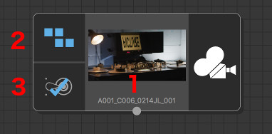
Along with the media thumbnail and the node name (which defaults to that of the loaded media) (1), this icon also indicates whether metadata is available to use in the media (2), and whether the media has been cached to disk (3).
When a Clip Input node is activated by double-clicking on it with the left mouse button, the PFTrack GUI will switch to display the Cinema Window, a single Viewer Window and the following important areas:
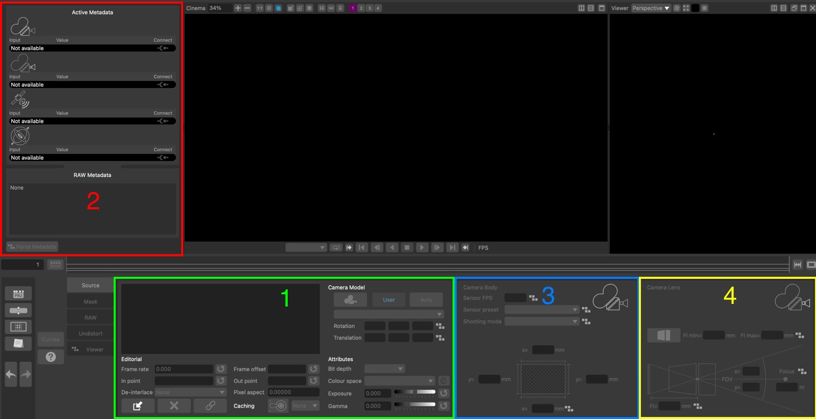
(1) The clip input menu buttons used to change the displayed toolset.
(2) The toolset selected from the menu buttons.
(3) The Camera Model panel, where the body and lens parameters can be set.
The Clip Input toolset is split into separate sections, selected by clicking a button in the input menu on the left of the panel.
Source: The source media information. This is also where media can be loaded from disk.
RAW: The RAW panel where parameters for decoding RAW media image data can be adjusted.
Metadata: The dynamic metadata viewer panel, showing metadata curves for any compatible metadata parameters.
Undistort: The Undistort panel where lens distortion correction parameters can be defined.
Mask: The mask panel where media containing a pre-rendered mask can be loaded from disk.
Source
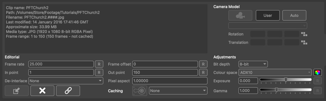
The source panel is where media can be loaded, and also lists important information about the source material such as its location on disk, frame numbering and duration.
Loading and removing media
 Load Media: Clicking this button will display the File Browser where the media can be located on disk and loaded into the node. By default, this will display the native file browser for your operating system for loading media files such as image sequences or movie clips. To open the file browser showing all files, hold the Shift key whilst clicking this button.
 Remove Media: Once media has been loaded, it can be removed if required by clicking this button. Note that media must be removed from the node before the node can be deleted from the tracking tree. This will remove the media from the Clip Input node, but will not affect any of the original media files on disk.
 Relink Media: If the location of media files on disk has changed since it was imported, the Cinema window will display Missing Media. Clicking this button will display the File Browser allowing the original source material to be found. Note that the clip resolution must be the same as the original clip in order for it to be re-linked. If you wish to change the resolution or relink a clip with different frame numbering, use the Replace Footage node.
Editorial
These controls are available to adjust the representation of the clip in PFTrack (Note that these will not affect the original media files on disk in any way).
- Frame rate: The number of frames-per-second for the clip. Clicking the Reset button  will reset the frame rate back to the default value for this clip.
- Frame offset: This can be used to offset the frame number that is read from the clip. For example, setting frame offset to +10 will mean that frame 1 of the clip displays frame 11 (1+10) of the source material.
- In point: Specify the first frame of the clip to use. Clicking the Reset button will reset the in point back to the original value.
- Out point: Specify the last frame of the clip to use. Clicking the Reset button will reset the out point back to the original value.
- De-interlace mode: The de-interlacing option to use for the clip. Replicate upper/lower will replicate new scanlines from either the upper or lower fields. Interpolate upper/lower will interpolate new scanlines from either the upper or lower fields. Blend will blend both upper and lower fields together. Temporal Blend will use motion analysis to align the upper and lower fields before blending. Field Separation will separate out the upper and lower fields and scale them up to fill separate frames, doubling the length of the clip.
Attributes
- Bit depth: This menu can be used to change the bit-depth of the media displayed in PFTrack. This can be used, for example, to change from 16-bit to 8-bit pixels and reduce the amount of RAM used to cache media.
- Colour space: This menu can be used to specify an OpenColorIO colour space for the clip, such as ACES 2065-1 or ACES CG. To use this option, OpenColorIO first must be enabled and configured in the System Preferences. Once a colour space is set, colour correction can be switch on or off on a per-clip basis by clicking the toggle button next to the colour space menu.
- Exposure: The exposure adjustment applied to image data. The Reset button will reset this back to the default value, which is 0.0.
- Gamma: The gamma adjustment applied to the image data. The Reset button will reset this back to the default value, which is 1.0.
Disk caching
If media is being loaded from an external resource (such as a network-attached drive), read performance may be reduced when compared to reading data directly from a local hard disk. In these situations, a local Disk Cache can be created in the System Preferences to improve read performance.
 : Clicking this button will cache the entire source media to the disk location specified in the cache menu. Once the source media is cached, the button icon will change to show that the media has been cached successfully:
  . Clicking the button again will clear the media from the disk cache and free the disk space used.
Note: Source media is cached at the desired bit-depth, but without any colour or lens distortion modifications which are applied after reading from the cache. To cache the media after these updates have been applied (or to cache only part of the original clip after changing in/out points), connect a Disk Cache node downstream.
Motion metadata
The Motion Metadata provides a readout of any camera rotation or translation data for the current frame that has been connected from the source media in the Metadata tools. This information is read-only, and is presented for the X, Y and Z camera axes.
RAW
The RAW panel contains parameters used to de-bayer RAW media clips and produce an RGB image. The controls in this panel are specific to the type of media loaded, and are only available for ARRI RAW and RED R3D media.
RAW debayering controls are available for ARRI and RED R3D files for Studio and Enterprise editions
ARRI RAW Decoding
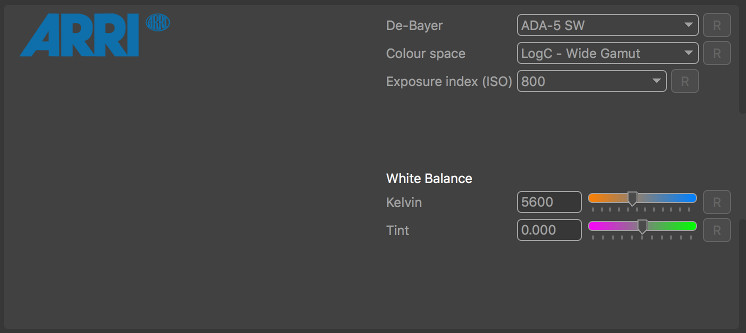
When reading ARRI RAW footage, the de-bayering algorithm used to convert ARRI RAW footage to an RGB image can be specified using the De-Bayer menu. Note that currently, only CPU-based decoding methods are supported. The colour space, ISO exposure index, White balance temperature and green/magenta tint will also be read automatically from the source media, although these values can be overwritten if required. For example, the exposure index of the shot can be decreased to provide more detail for feature tracking if necessary.
- De-Bayer: The de-bayering algorithm used to convert an Arri RAW file to RGB. Note that GPU-based de-bayering is not currently supported, and CPU performance of some de-bayering algorithms is faster than others.
- Colour space: The colour space used when decoding.
- Exposure index (ISO): The ISO exposure index used when decoding.
- White balance (K): The colour temperature of the white balance used when decoding.
- Tint: The green/magenta tint of the white balance used when decoding.
-  : Reset any parameter back to the value specified in the source material file.
RED R3D Decoding
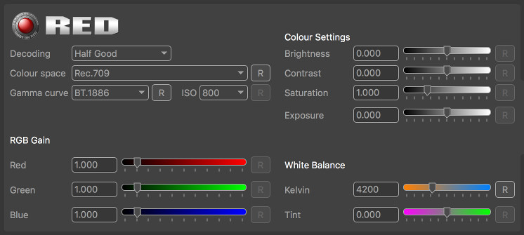
When reading RED R3D footage, various decoding parameters can be selected to choose between higher quality or faster decoding, along with using 8 or 16bit pixel data. Colour space and white balance can also be adjusted, along with exposure and brightness/contract controls.
- Decoding: This menu provides choice between a slower but more accurate de-bayer algorithm (Full Premium) and faster algorithms such as Half Premium, Half Good and Quarter Good.
- Colour space: The colour space used for decoding to be changed.
- Gamma curve: The gamma profile when decoding.
- ISO: The ISO value used when decoding.
- Brightness: The brightness adjustment.
- Contrast: The contrast adjustment.
- Saturation: The saturation adjustment.
- Exposure: The exposure adjustment.
- RGB Gain: The gain parameters in the red, green and blue channels.
- White balance: The colour temperature for white balance adjustment.
- Tint: The overall tint of the white balance adjustment.
- : Reset any parameter back to the value specified in the RED R3D file.
Metadata
The Metadata toolset is displayed by clicking the Metadata button on the left of the Clip Input panel.
Metadata is useful information recorded by a movie camera whilst shooting. It often comprises data such as the camera focal length, sensor size, or shooting mode, and may even contain information about how the camera is moving during the shot. Metadata can often be used to help track shots more easily, especially when data such as the camera focal length is available.
PFTrack currently supports metadata embedded in media files such as:
- RED R3D files (Studio/Enterprise editions only)
- ARRI RAW (Studio/Enterprise editions only), Quicktime ProRes, DPX or OpenEXR files containing ARRI Metadata
- OpenEXR files containing metadata from any supported application.
If the source media contains metadata that can be used in PFTrack, it will be displayed in the Available Parameters panel.
Raw Metadata
The full list of all metadata in the media is available in the RAW Metadata window that is displayed by clicking the Raw Metadata button: 
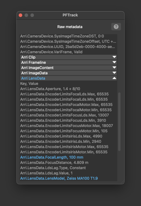
The important values that PFTrack has identified are highlighted in blue. Individual sections of the RAW Metadata list can be opened and closed using the white arrow buttons to the right of each section title. All RAW metadata can be accessed down-stream from the Clip Input node using Python scripting if required.
If raw metdata is visible in your media but is not picked up by PFTrack, you can configure which keys and values to read using the metatags XML file. Further information about how to tell PFTrack which metadata is important for your media is available in the Metadata Tags section.
Parsing Metadata
Many types of metadata may vary from frame-to-frame (for example, the camera focal length, or the IMU rotation). Before this metadata can be used, the entire clip must be processed so that the metadata values for each frame can be parsed and analysed. This is achieved by clicking the Parse Metadata button: 
Once metadata has been parsed, if information such as the camera focal length has been identified, it will be displayed in the appropriate section of the Active Metadata Window.
Available Parameters
The Available Parameters panel contains important metadata values that PFTrack has identified and is able to use:
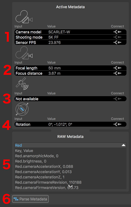
Each section displays the metdata Key in the left column, the metadata value in the middle column, and has a Connect toggle  on the right.
- Body : containing information related to the camera body and sensor.
- Lens : containing information related to the camera lens.
- GPS : containing information related to the GPS position.
- IMU : containing information captured by on-camera IMU devices.
Note that not all file formats support all types of metadata. If no metadata is available that is relevant to each section, it will be displayed as Not available.
Body Metadata
Camera body metadata generally comprises of information used to help identify the size of the camera sensor (or film back). This information is essential to PFTrack when using camera focal lengths measured in real-world values such as millimeters, as it helps PFTrack to convert a focal length in millimeters into a horizontal or vertical field of view.
MXF metadata generated by the Sony RAW Viewer application (and supported by PFTrack via OpenEXR files) contains the exact sensor size used by the camera. All other supported metadata formats only contain information such as the camera model and shooting mode, which are used as hints to help PFTrack identify a suitable sensor size from a fixed set of presets.
Further information about the relationship between focal length and sensor size is available in the Camera Model section.
Lens Metadata
Camera lens metadata typically comprises of information such as the focal length and focus distance. In order to use the camera focal length correctly, PFTrack must also know the camera's sensor size.
Further information about the relationship between focal length and sensor size is available in the Camera Model section.
GPS Metadata
GPS position metadata comprises of data specifying the latitude, longitude, and possibly altitude of the camera.
IMU Metadata
In addition to GPS metadata describing the camera position, IMU data may be available that describes the camera orientation. This may come from either the camera body, or the camera lens depending on the types of camera and lens being used.
Connecting Metadata
If metadata is available to use, it must be connected to PFTrack's virtual camera in order to assist with any operations such as camera tracking. This is achieved by clicking the Connect toggles next to each piece of metadata.
Due to the nature of how metadata is often recorded by the camera, the values present in the files may not always be as accurate as is needed for the purposed of matchmoving. For example, there may be a lag between recording the image frame and the focal length of the camera at that exact time, or there may be quantization or calibration issues with the recording devices. Because of these inherent problems, PFTrack is able to use metadata as either a hint or an exact value.
Clicking the Connect toggles will cycle between three states:
 : When in this state, metadata is not connected and does not affect the camera (this is the default state).
 : This state indicates the metadata value is to be used as a Hint to the camera.
 : This state indicated the metadata value is to be used as an Exact value in the camera.
Not all states are available for each camera input. Further information on how metadata affects the camera in PFTrack is available in the Camera Model section.
Metadata graph
The metadata graph can be used to display metadata parameters that vary per-frame, such as camera focal length or IMU rotation data. This can be useful to check for any potential issues with the metadata values before connecting them to the camera.
To display a metadata parameter, enable it in the Available Parameters list by clicking the indicator next to the Value column:
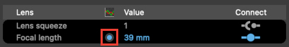
The graph display will remain centered on the current frame. As the mouse is moved over the graph, a floating indicator will appear showing the metadata parameter key and value.
The graph can be panned vertically using the right mouse button, and zoomed using the middle mouse button or mouse wheel:
- Click and drag the yellow frame marker with the left mouse button to change frames.
- Click and drag with the middle mouse button to zoom the graph horizontally or vertically.
- Click and drag with the right mouse button to scroll the graph vertically.
To fit the graph display to the metadata curve, click the  button:
Undistort
The Undistort panel can be used to specify how lens distortion should be corrected for. It is also the place where OpenEXR ST-maps can be loaded from an external source and applied to the clip.
The Mode menu is used to specify how to correct for lens distortion for this clip:
- None: No lens distortion correction will be applied.
- Preset: If a camera preset is being used, selecting this option will take the lens distortion model from the camera preset and use it to undistort the clip. If the lens distortion model is constant, or the camera focal length is known at this time, the clip will be undistorted immediately. If not, lens distortion will be corrected for down-stream once the camera focal length is known (e.g. after the camera has been solved).
- Automatic: When this option is selected, the amount of lens distortion will be estimated automatically and removed once the camera has been solved.
- Measured: Selecting this option will enable the measurement tools and allow lens distortion parameters to be measured directly from the image (see below for further details). Once distortion has been measured, it will be removed from the clip immediately and the undistorted clip passed down-stream for tracking.
- ST-Map: Selecting this option will allow OpenEXR ST-maps to be loaded from an external source and applied immediately to the clip to remove lens distortion. The undistorted clip is then passed down-stream for tracking.
Note that when changing lens distortion correction in the Clip Input node, any tracking points that have already been created downstream will be adjusted automatically to compensate. There is no need to track feature points again.
ST-Maps
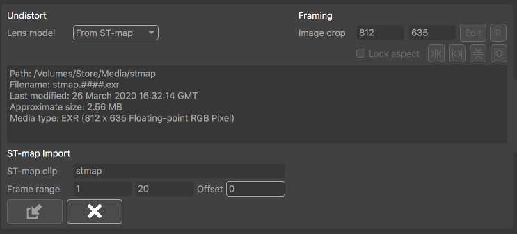
In order to load an external OpenEXR ST-map from disk, select From ST-Map from the Mode menu. Media can be managed using the following buttons:
- : Open the File Browser to load an ST-Map clip.
- : Clicking this button will remove the ST-Map from the Clip Input node (Note this will not affect any of the source material files on disk).
If the frame-range of the ST-Map clip does not match the frame-range of the clip to be undistorted, the first and last frames of the ST-Map clip will be held. The resolution of the undistorted clip will be defined by the resolution of the ST-map clip. Note that this will affect the sensor area and field-of-view displayed in the Camera panel.
- ST-map clip: This displays the name of the clip providing the ST-map, if available.
- Frame range: This displays the first and last frame of the ST-map source material.
- Offset: Shift the source material forwards or backwards by a specified number of frames.
Measured distortion correction
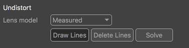
If no ST-maps or camera preset are available to provide information about lens distortion, the clip can still be undistorted directly in the Clip Input node provided the source material contains one or more straight lines that are distorted by the camera lens. For example, this might be a vertical line on the edge of a doorway, or the horizontal line of a brick wall.
In order to measure and correct for lens distortion, select Measured from the Mode menu. This will enable the Draw Lines button. Clicking this button will allow a straight line to be draw in the Cinema window along an image edge that should be straightened.
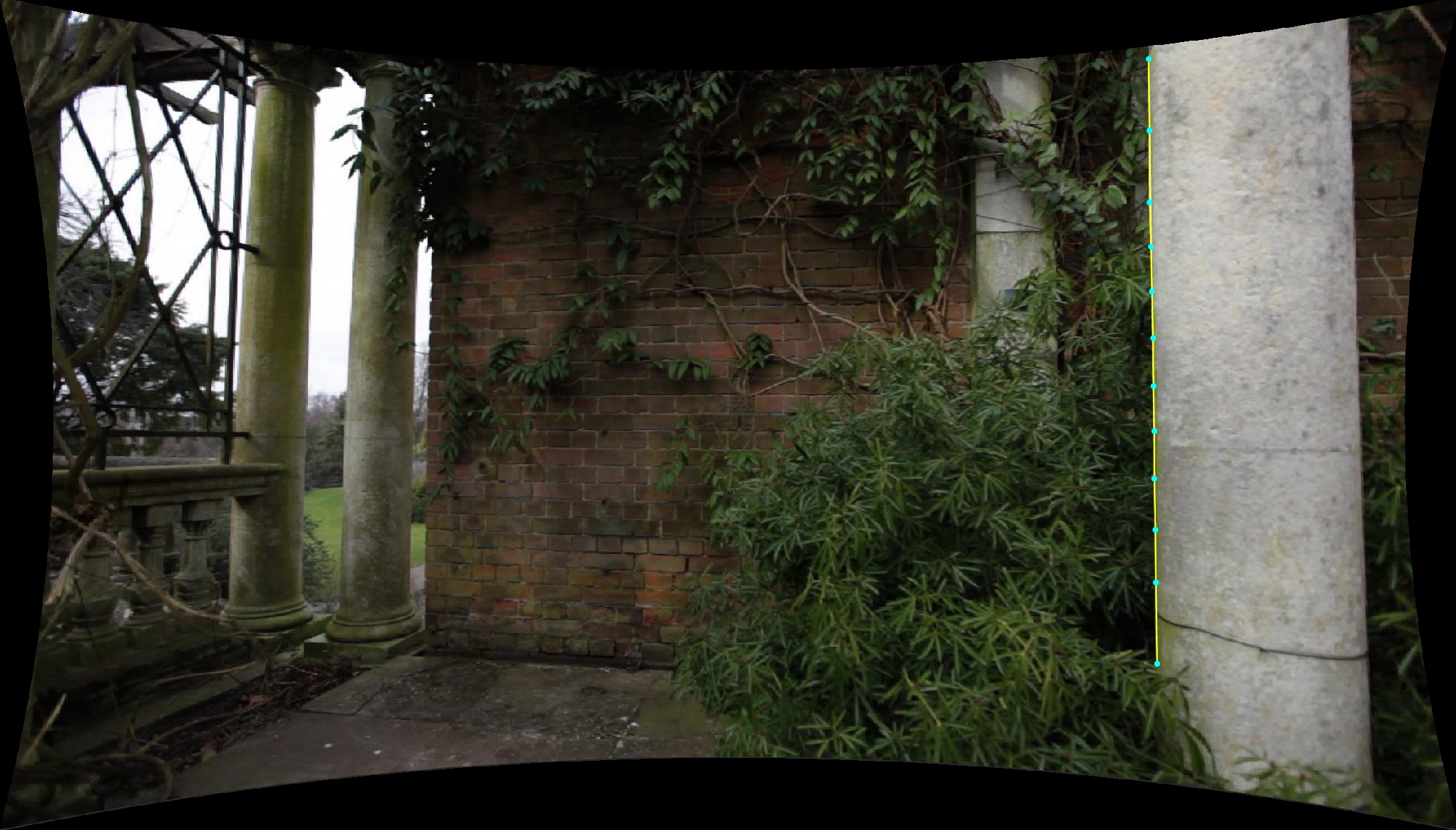
A line is drawn by:
- Clicking and releasing the left mouse button to place the start point of the line (1),
- Moving the mouse to the end point and clicking and releasing again (2).
Once the initial line is placed, additional vertices must be inserted into the line by clicking and dragging with the left mouse button (3). Each additional vertex should be positioned to trace alone the curve of the line that is to be straightened, as shown in the following image:
More than one line can be drawn if required, and lines can be placed in different frame of the clip. Holding the Shift key whilst positioning a point will display a window showing a closeup of the image pixels.
Clicking the Solve button will solve for lens distortion. If distortion can be corrected accurately, the line traced in the source material will be straightened as shown below:
Coefficients can be entered directly into the Coefficients edit boxes if available.
Framing
After a clip has been undistorted, controls are available to adjust image cropping if required.
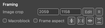
By default, a clip will undistort to the same resolution as the original frame. This means some pixels will be lost around the boundary of the image. Adjusting the image crop size will allow these pixels to be recovered if desired. This can have an effect on how ST-Maps are exported, and further details about ST-Map export are available in the Scene Export node
- Image crop: This displays the current width and height of the undistorted image.
- Edit: Selecting this button will allow the image crop area to be adjusted manually in the Cinema window by clicking and dragging on the frame boundary with the left mouse button.
- : Clicking this button will reset the image crop to match the original source material resolution.
These buttons will expand the image as much as possible to include all undistorted pixel at the image border:
-  : Clicking this button will fit to the full horizontal extents of the undistorted image.
-  : Clicking this button will fit to the full vertical extents of the undistorted image.
These buttons will expand the image to discard empty pixels at the image border:
-  : Clicking this button will fit horizontally to ensure no empty pixels are visible at the left and right-hand edges of the image.
-  : Clicking this button will fit vertically to ensure no empty pixels are visible at the top and bottom edges of the image.
Note: these options are not available when using an ST-map as the size of the displayed image area is defined by the OpenEXR 'display window' area, as described in the Scene Export node.
Re-applying lens distortion
If lens distortion needs to be re-applied to a clip, instead of removed, this can still achieved in PFTrack using these tools. After tracking, use the Scene Export node to export ST-Maps suitable for both undistort and redistort.
Then, instead of using your redistort ST-Maps in a third-party composing application to re-apply lens distortion, just load your undistorted elements into a new Clip Input node, select From ST-Map as described above and load the ST-Maps generated for redistort.
This will recover images a the original frame size with lens distortion re-applied. These can then be exported down-stream using the Footage Export node.
Mask
The Mask panel is where image-based masks can be loaded and applied to the clip. By default, the source material for the mask will be scaled to fit both the clip resolution and the number of frames. Once an image-based mask is loaded, it will be passed down-stream automatically to each node which can make use of it.
Note in addition to image-based masks, both Spline and Keyer masks can also be generated and connected to any node down-stream from the Clip Input node.
- : Open the File Browser to load a mask clip.
- : Clicking this button will remove the mask from the Clip Input node (Note this will not affect any of the source material files on disk).
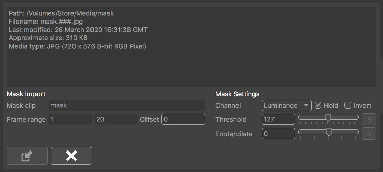
- Mask clip: This displays the filename of the mask clip when loaded.
- Frame range: This displays the first and last frame of the mask source material.
- Offset: Shift the source material forwards or backwards by a specified number of frames.
- Channel: Specify which image channel is used to create the mask from the source material. Options are Red, Green, Blue and Alpha to select one image channel, or Luminance to calculate pixel luminance.
- Hold: When enabled, frames outside of the original source material range will be clamped, so the first and/or last frames of the source material will be held. When disabled, frame outside the original range will not display any mask.
- Invert: Invert the mask in the clip.
- Threshold: This specifies the pixel threshold (measured as a 8-bit value in the range 0..255) which is used to convert a grey-scale image into a binary mask. Pixel values less than the threshold are set to be transparent, and values greater are set to be opaque.
- Erode/dilate: Erode or dilate the mask. Positive values will dilate the mask, whilst negative values will erode.
Once an image-based mask is loaded, it can be used downstream in any node which supports other types of mask. Where supported, the masks in the node can be toggled on or off as required, or inverted if necessary by using the mask button  in the node's control panel. This button can be toggled between three states:
-  : Indicating that any masks connected to the node should be used
-  : Indicating that any masks connected to the node should be used, but they should be inverted first of all
-  : Indicating that any masks connected to the node should be ignored.
Camera Model
In order to perform matchmoving tasks, PFTrack must create a Virtual Camera Model that matches the real camera as closely as possible. The tools available in the Clip Input node are used to define this virtual camera model including parameters such as:
- The camera sensor size
- The camera focal length
- The type of lens distortion correction
This information may be available as metadata in your media files, or may be specified manually. If no information is available, PFTrack can also attempt to estimate the data automatically.
The following areas are available to specify these parameters:
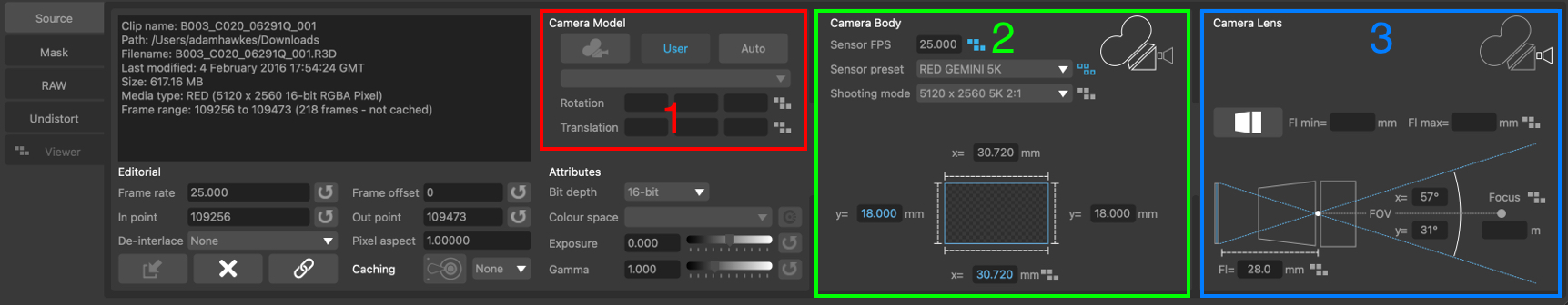
(1): The Camera Model parameters, chosen as either User for a user-defined camera, or Preset to define the camera using a preset.
(2): The Camera Body parameters, including most importantly the sensor size for the frame.
(3): The Camera Lens parameters, including focal length and lens squeeze information.
User and Preset mode
When PFTrack attempts to track the camera, it must estimate various camera parameters such as the position and orientation at each frame, along with the camera focal length and lens distortion if necessary. This is a complicated process, and as such it helps to specify as much information about the camera as possible beforehand.
The Camera Model options are used to specify this information, and there are two options available, User and Preset:
User mode
User mode is the default, and allows information about the camera sensor size and focal length to be entered manually or by connecting metadata. Initially, both the camera body (i.e. sensor size) and focal length are set to Unknown. This means focal length of the camera will be estimated automatically.
If the camera sensor size is known, it can be entered in the Camera Body section. Alternatively, online or offline databases can be searched to locate a suitable sensor size for your camera. Once the sensor size is known, the camera focal length can also be entered in the Camera Lens section if it is available. The lens squeeze factor should also be entered.
When in User mode, lens distortion removal can be specified in the Undistort panel.
Preset mode
The Preset mode provides the most reliable approach to matchmoving, because camera presets contain more accurate information about lens distortion that is used directly during the matchmoving process.
When Preset mode is enabled, camera lens metadata can still be used to describe the focal length changes of azoom lens. Hints about camera rotation or translation can also be provided if appropriate metadata is available.
Further information on how to build camera presets is available in the Camera Presets section.
Camera Body
The Camera Body panel contains information related to the camera model, shooting mode, and sensor area. If the camera lens focal length is known in millimeter, the Active area of the camera sensor must be entered here:
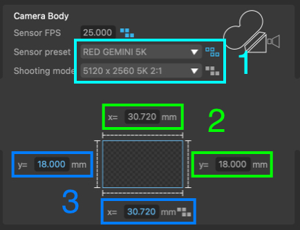
Note: It is important to ensure the camera sensor area is entered correctly, as it is used alongside the focal length (in millimeters) to calculate the field of view of the virtual camera that PFTrack is using. If either the sensor size or focal length values are incorrect, the field of view of the virtual camera will not match that of the real camera and this will cause problems and errors during the matchmoving process.
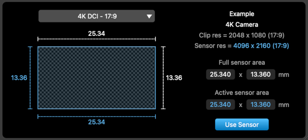
Sensor area
To enter a known sensor size, click the Known button and enter the Active area of the sensor in millimeters.
If you are unsure of the sensor area for your camera and footage, click the Sensor Search button  to open the search window. This provides access to various online databases containing sensor sizes for many commonly used cameras and shooting modes, including The Pixel Farm's online database.
Further information about searching for a suitable sensor size is available on the Sensor Database page.
Note that the active area corresponds to the area of the sensor covered by your frame, which is not necessarily the same as the full area of the camera sensor, for example.
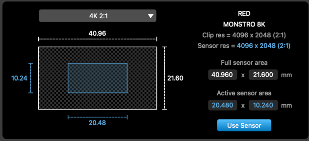
- Windowed Sensors: A camera may only expose part of the full sensor when in certain shooting modes. For example, a RED MONSTRO 8K sensor has an overall size of 40.96 x 21.6 mm, and the full sensor area is used when shooting at 8K 8192 x 4320 resolution. However, as this camera employs a windowed sensor, shooting in 4K mode at 4096 x 2048 only exposes part of the sensor, and this area is 20.48 x 10.24 mm. This reduced sensor size should be used when tracking footage shot in 4K mode on this camera.
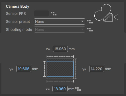
- Scaled Sensors: Other cameras may expose as much of the sensor area as possibe, depending on the aspect ratio of the frame in different shooting modes. In these cases, generally the top and bottom of the frame are cropped to ensure the aspect ratio of the frame fits to the full sensor width. For example, a camera may have a full sensor with an aspect ratio of 4:3, and a sensor size of 18.96 x 14.22mm. When shooting in HD mode at 1920 x 1080, if the sensor is scaled then the correct sensor area must actually be 18.96 x 10.665 mm to match the 16:9 aspect ratio of the frame:
- Proxy resolutions: Finally, care must be taken if the clip being tracked has been scaled or otherwise adjusted after capture. For example, when shooting at 4K resolution and then scaling to a 2K proxy, make sure to enter the sensor size for the original 4K footage. This ensures the field of view of the camera using your 2K proxy clip is the same as the original 4K footage:
Custom sensor presets
If you wish to create a custom sensor preset for a sensor that is not available in any online database you can do this easily by creating a small XML file, and this information will them become available in the sensor search window. Further information about sensor preset files is available here.
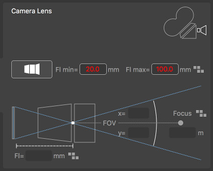
Camera Lens
The Camera Lens panel contains information related to the camera lens, such as the type of lens being used and its focal length:
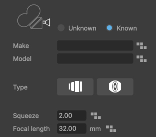
The type of camera lens can be specified as follows:
 : This icon indicates a prime lens is being used, and the virtual camera will has a constant focal lengthh for the entire shot.
 : This icon indicates a zoom lens is being used, and the focal length will be allowed to vary throughout the shot.
 : This icon indicates a spherical lens is being used.
 : This icon indicates an anamorphic lens is being used, and the Lens Squeeze factor should be set appropriately for your lens.
If focal length metadata is available and has been connected, the type of lens and focal lengths will be updated automatically, and the metadata indicators next to each value will show whether the metadata is being used exactly as specified or as a hint.
Prime Lenses
Prime lenses have a fixed focal length. If this focal length is known, it can be entered into the Focal Length edit box. Once the focal length is entered, the field of view of the virtual camera used by PFTrack will also be displayed.
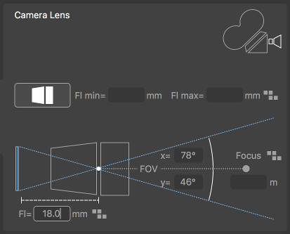
Zoom Lenses
Zoom lenses are able to change focal length over the course of the shot. Focal length will vary between the Focal Range minimum and maximum values, which must be entered in the edit boxes.
Connected Metadata
When metadata is available in the loaded media, it can be connected to the virtual camera model using the Connect toggles in the Available Parameters.
As metadata is connected, the metadata indicators next to each parameter will change according to how the metadata is being used:
 : This indicates that no metadata is connected to the camera parameter.
 : This indicates that metadata is connected, but is potentially unreliable and therefore only being used as a hint.
 : This shows that metadata is connected and the metadata value is being used exactly as specified in the media.