| Studio / Enterprise | PFTrack Documentation | Node Reference |
Mocap Solver
Usage | Controls | Trackers | Residual Errors | Coverage | Editing Trackers | DisplayNote: this node is only available with Studio or Enterprise editions
The Mocap Solver node can be used to obtain the motion of individual tracking points viewed from two or more camera positions. This is often used to track the motion of an actor's body or face, where tracking points have been identified using physical markers.
In contrast to standard object tracking, the Mocap Solver node does not assume that the object is moving in a rigid fashion. The motion of each tracking point is completely independent and can therefore represent movement of non-rigid objects.
The Mocap Solver node can have multiple inputs, each corresponding to a different camera view of the subject. The first input is the primary camera, and the second (or third etc..) inputs correspond to witness cameras. The witness cameras can be at a different resolution to the primary camera, but must have the same frame-rate.
Usage
In order to solve for tracker motion viewed by multiple cameras, it is important to ensure that the frame numbers of witness cameras match those of the primary camera. If this is not the case, adjust the in/out points or frame offset of the witness camera in its Clip Input node so that the each frame of the witness camera is viewing the actor at the same point in time as the primary camera. To help with this, it is often useful to identify a reference event such as an eye blink or other action, and use that to synchronise the witness cameras to the primary.
Trackers should be tracked with a User Track node, making sure that each tracker is tracked in at least two of the input clips. The screenshot below shows how a User Track node should be connected to two input clips (the primary camera and one witness camera), and then to the Mocap Solver node:
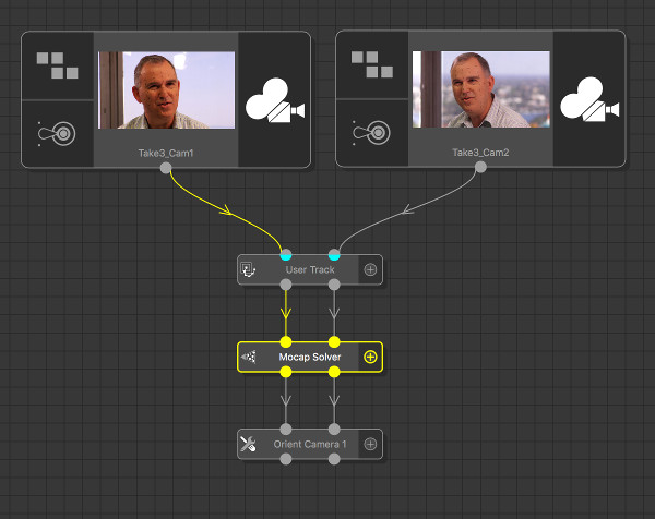
The screenshot below shows several tracker that have each been tracked in both the primary and witness cameras:
![]()
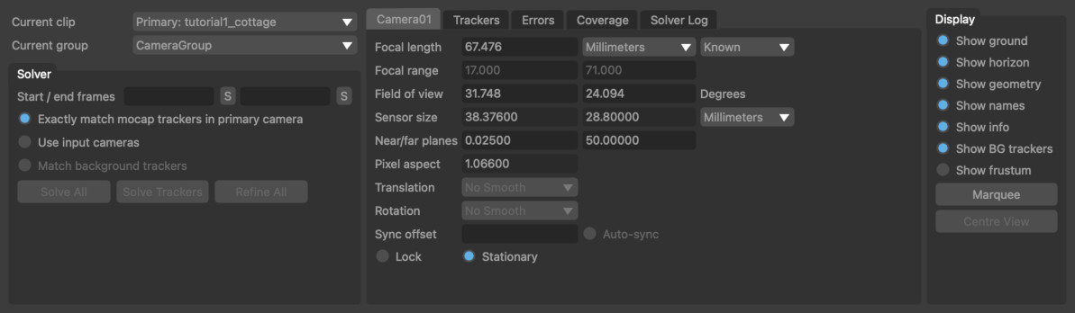
Once trackers have been created, information about the primary and witness cameras must be set in the Mocap Solver node. If focal length information is available for either the primary or witness cameras, entering that data will help the solver produce a more accurate result.
Note that when entering a focal length in a physical unit such as millimeters, it is important to first ensure the sensor/film back size are correct for your camera sensor. This can be set in the Clip Input node.
In order for the mocap solver to estimate the position of the tracking points in 3D space, the witness cameras must be stationary (i.e. they must not translate or rotate, and must have a constant focal length). If only one witness camera has been used then the primary camera must also be stationary. If two or more witness cameras are used, then the primary camera is allowed to move.
Once solved, trackers are shown in the Cinema window coloured according to how well their projected position matches their 2D tracker locations. Trackers that match their 2D location well (with a residual error less than 1 pixel) are coloured green, trackers with residual errors less than 2 pixels are coloured orange, and trackers with residual errors larger than 2 pixels are coloured red. An error line is also drawn connecting the projected tracker position with its 2D tracker location.
Tracker Groups
All the trackers generated by tracking node such as Auto Track or User Track will be placed into a single Tracker Group for each node and passed downstream into the Mocap Solver. The Tracker Groups control should be used to select which tracker groups to use to solve for. By default, all input groups are enabled.
If you wish to rename the tracker groups, this should be done by renaming the node in the Workpage.
Motion Capture Using Pre-Solved Cameras
When the primary camera is moving and viewing a scene containing enough tracking markers, better mocap results can often be obtained by solving for the camera positions before using the Mocap Solver node.
This can be done using the Camera Solver node to solve for the position of the primary and witness cameras, feeding the results into a User Track node to track the mocap markers, and finally attaching a Mocap Solver node. The mocap tracker positions can then be generated by either:
- Enabling the Use Input Cameras option and clicking the Solve All button.
- Clicking the Solve Trackers button to solve for the tracker positions only.
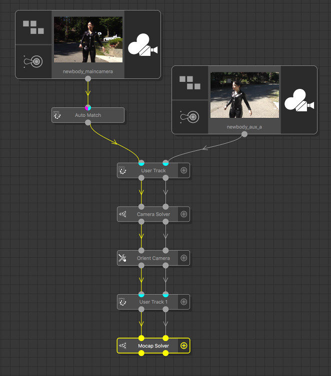
The following screenshot shows an example tree used for motion capture with a pre-solved moving primary camera and one witness camera (footage from hollywoodcamerawork.com/trackingplates.html). The Auto Track and User Track nodes were used to create features for tracking the motion of the primary camera and the position of the witness camera in the Camera Solver node. The User Track 1 node was then used to create trackers for mocap.
Controls
Current clip: The clip that is being displayed in the Cinema window.
Solver
Tracker groups: The tracker groups that will be used to solve for motion capture. Each upstream node used to generate trackers will provide a single group, and these can be enabled or disabled as required when solving.
Start/end frames: The start and end frames to use for motion capture. The S button will store the current frame number as either the start or end frame.
Exactly match mocap trackers in the primary camera: When enabled, the position of mocap trackers in 3D space will be set to exactly match the tracker path in the primary camera during solve and refinement operations. Note that it will often be the case that doing this will increase the error in the witness cameras. When this option is not enabled, the error will be spread as evenly as possible between the primary and witness cameras.
Use input cameras: When enabled, the cameras that are input to the Mocap Solver node will be used to solve for the tracker positions. Enabling this option will lock the input primary and witness cameras so they are not changed during the mocap solve.
Match background trackers: When trackers have been used up-stream to solve for the position of the primary and/or witness cameras, enabling this option will mean that these trackers are taken into consideration when trying to minimise the error during refinement, in addition to the trackers used for motion capture. Note that in order for an up-stream camera position to be modified during refinement, it must be un-locked in the Camera parameters tab.
Solve All: Solve for camera and tracker positions. The motion capture solve can be run in the background by holding the Shift key whilst clicking on the Solve All button.
Solve Trackers: Solve for motion capture tracker positions only. This can be used in situations where new trackers have been added up-stream and need to be solved using the existing camera positions..
Refine All: Adjust camera and motion capture tracker positions to better match the tracker paths. Refinement can be run multiple times, and a longer refinement can be ran by holding the Shift key whilst clicking on the button.
Camera
The camera control tab contains information about the camera associated with the current clip. If more than one input clip is present, the current camera (and clip) can be changed using the Current clip menu option.
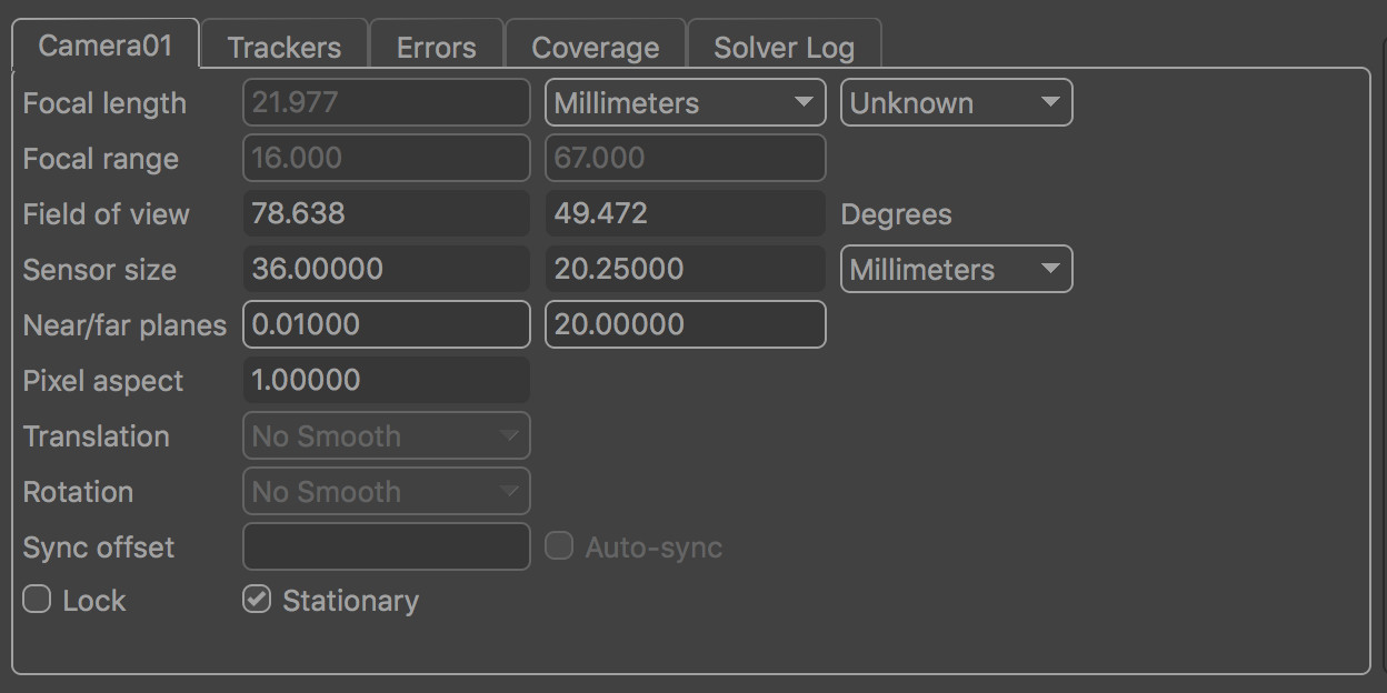
Focal length: The camera focal length at the current frame. Focal length can be set as Known, Unknown or Initialised. If the focal length of the camera is known beforehand, entering the value here can often improve both the speed and accuracy of the mocap solver. Setting focal length to Initialised will allow a minimum and maximum value to be specified in the Focal range edit boxes, and an initial value to be entered into the Focal length edit box. Note that in order to enter a focal length measured in any unit other than Pixels requires that the camera sensor/film back size is set correctly
Focal range: When focal length is set to Initialised, these edit boxes define the minimum and maximum allowable values of focal length.
Field of view: The horizontal and vertical field of view at the current frame, measured in Degrees.
Sensor size: The horizontal and vertical sensor/film back size. To change sensor size, edit the camera preset values in the Clip Input node.
Near/far planes: The near and far camera clipping planes.
Squeeze: The current lens squeeze ratio. To change the squeeze ratio, edit in the Clip Input node.
Translation: The smoothness of the camera translation path. This option is only available for a non-stationary primary camera. Smoothing options are None, Low, Medium and High.
Rotation: The smoothness of the camera rotation path. This option is only available for a non-stationary primary camera. Smoothing options are None, Low, Medium and High.
Sync offset: The temporal offset to apply to the witness camera during the mocap solve. This edit box is only available for witness cameras. This is used to correct situations where there is a small difference between the times at which the witness camera captured frames, compared to the primary camera. Setting this value to 0.5 means that the actor viewed by the primary camera at frame N is in exactly the same position when viewed by the witness camera at frame N+0.5.
Auto-sync: When enabled, the temporal sync offset will be calculated automatically during the mocap solve.
Lock: When enabled, the position and orientation of the camera will be locked to prevent adjustment when refining the solve.
Stationary: Assume the primary camera to be stationary. This option is only available for the primary camera. This information is used to help improve the accuracy of the mocap solve. All witness cameras are assumed to be stationary.
Trackers
![]()
The tracker list contains information about all trackers passed into the mocap solver node.
Columns
Name: The tracker name.
Active: Indicates whether the tracker is active in the mocap solver or not. To activate or de-activate multiple trackers at the same time, select them and click the Activate or Deactivate buttons on the right of the tracker list.
Rigid: Indicates that the tracker is moving in a rigid fashion with respect to all other trackers that have this flag set. This is used to help improve the accuracy of the mocap solver. For example, when placing trackers on an actor's face, it is often the case that points on their forehead are all moving in a rigid fashion with respect to each other.
Weight: The weight given to a particular tracker in the solution. The default value is 1.0, but increasing this will mean the mocap solver expends more effort to match a 3D tracker position to its path, possibly at the cost of decreased accuracy elsewhere. Changing the tracker weight can often help to lock a solution down onto a particular tracker.
Residual: The residual error measured in pixels (also knows as the reprojection error) for the tracker in the current frame. The residual error is the difference between the tracker path position and the projection of the 3D tracker point onto the camera plane. Ideally, the residual error should be close to zero for each tracker.
Distance: The distance from the current camera frame to the tracker's 3D position in space. This can be useful to detect when the mocap solver has failed to determine which trackers are in the foreground and which are in the background.
Controls
All / None: Select all or none of the trackers from the list.
Activate: Activate all selected trackers in the mocap solver. Active trackers will contribute to the solution. Trackers can also be activated individually by ticking the Active column in the tracker list.
Deactivate: Deactivate all selected trackers in the camera solver. Inactive trackers will not contribute to the solution. Trackers can be deactivated individually by un-ticking the Active column in the tracker list.
Adjust: Click the Adjust button to make adjustments to the selected tracker in the Cinema window. Further information is available in the Tracker Adjustment section.
Smoothing: The amount of smoothing to apply to each mocap tracker in 3D space. The available options are None, Low, Medium and High. When smoothing is enabled, jitter on the 3D tracker position will be reduced.
Residual Errors
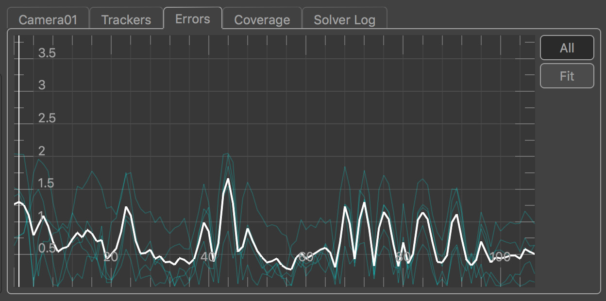
The error graph plots the residual error measured in pixels for each tracker in each frame, along with the average residual error for all trackers visible in a frame. The residual error (also known as the reprojection error) is the difference between the tracker path position and the projection of the 3D tracker point onto the camera plane. Ideally, the residual error should be close to zero for each tracker. Selected trackers are shown in yellow, and unselected trackers are shown in blue. The average residual error graph is shown in white. The error graph can be translated and scaled by clicking and dragging with the right or middle mouse buttons.
Individual trackers can be selected from the graph by clicking with the left mouse button. When a tracker is selected, the current frame will change to match the frame number that was clicked in the graph. If the Centre View display option is also enabled, the main image window will be panned to display the tracker projection in the centre. Multiple trackers can be selected at once by either holding the Ctrl key whilst clicking, or by clicking and dragging with the left mouse button to draw a selection rectangle.
If a tracker has been tracked accurately but has a residual error that increases significantly in certain frames, it often indicates that the camera position or focal length in those frames is incorrect. Adding more trackers to the solution, or providing estimates of camera focal length can often help out here.
Click and drag right mouse button in error graph to pan the graph. Click and drag middle mouse button in error graph to zoom the graph (or use the mouse wheel, holding Alt/Option to zoom vertically instead of horizontally).
All: When enabled, error graphs will be shown for all trackers, otherwise graph will only be shown for selected trackers.
 : Click the Fit Area button to draw an area in the graph with the left mouse button and fit the viewport to that area.
 : Click the Fit button to scale and translate the error graph so all graphs are visible.
Adjust: Click the Adjust button to make adjustments to the selected tracker in the Cinema window. Further information is available in the Tracker Adjustment section.
Coverage
The Coverage Panel displays information about the frames in which each tracking point has been tracked. This can be used to evaluate how well tracking points are distributed throughout the clip, which will help to provide an accurate camera solve without any jumps in the camera path.
Coverage Keys display
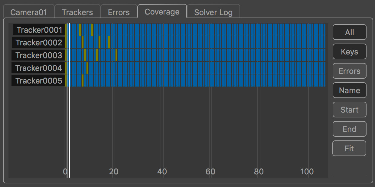
By default, the Coverage Panel displayed keyframe information showing how tracking points have been positioned and tracked. Each frame in which the tracker is present is shown with a blue square. Yellow squares show frames in which manually generated tracking points were keyframed.
Frames in which the tracker is visible but has not been positioned are displayed in dark red. It is important to ensure that tracking points have been positioned in all frames in which they are visible, as this can significantly affect the accuracy of the camera solve.
Coverage Error display
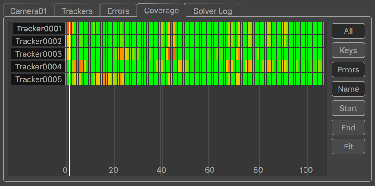
Alternatively, the Coverage Panel can also display the residual error for each tracker by clicking the Errors button. This switches the colour-coding of each indicator to show the error of the solved tracking point in each frame. This is colour-coded to show green for less than 0.5 pixels error, yellow for 1.5 pixels and red is greater than 2.5 pixels.
Coverage Panel controls
The Coverage Panel can be panned horizontally or vertically by clicking and dragging with the right mouse button. Clicking and dragging with the middle mouse button will zoom either horizontally or vertically to increase the number of tracking points and frames that are displayed in the panel.
The mouse wheel can also be used to zoom horizontally, or vertically if the Alt/Option key is held.
Clicking on an indicator with the left mouse button will select the tracking point and display that frame in the Cinema window. Holding the Ctrl key will allow multiple tracking points to be selected.
Double-clicking on an indicator with the left mouse button will select the tracking point and immediately switch to display the node which generated that tracking point. This can be used to quickly jump to a User Track node to manually adjust a tracking point to correct a tracking error.
All: Switch between displaying all trackers, or only those trackers visible in the current frame.
Keys: Display keyframe information, showing where targets have been tracked and manually positioned.
Errors: Display residual error information.
Name: Sort the tracking points by name, in alphabetical order.
Start: Sort the tracking points according to the first frame in which they are tracked.
End: Sort the tracking points according to the last frame in which they are tracked.
Adjust: Adjust the selected tracking point in the Cinema window using the Tracker Adjustment tools .
 : Fit the tracking points display to the window. This will zoom in or out as necessary, displaying as many tracking points and frames as will fit in the viewport.
Editing trackers
The Residual Errors tab will display a graph showing the residual errors for each tracker, along with the average error for all trackers in white. Trackers can be selected from here by clicking in the graph with the left mouse button, or by clicking in the Cinema window or using the selection Marquee.
The Coverage tag will also display keyframe and residual error information for each individual tracker.
Editing the original tracking points can be done in an upstream User Track node. Alternatively, local adjustments to the tracking points can also be made directly in the Mocap Solver node using the Tracker Adjustment tools.
Tracker Adjustment
![]()
The tracker adjustment buttons appear in the Cinema window when a tracker is selected for editing by clicking the Adjust button. The Cinema will zoom in to centre on a closeup of the tracking point.
Whilst zoomed in, the tracker position, window, or search window can be adjusted in the Cinema using the left mouse button.
The default interaction to change the tracker position is click and drag the background image to align with the tracking point.
Alternatively, if you prefer to click and drag inside the tracking window to move to tracker whilst keeping the background image fixed, disable the move background instead of tracker option in the Cinema/Viewer preferences window.
The size of the window (or search area) can adjusted by moving an edge or corner. Hold the Ctrl key to adjust the window asymmetrically.
The Alt/Option keyboard modifier can be held to ensure only the tracker position is changed, regardless of the mouse position. This behaviour can be reversed in the User Preferences window if desired, so the modifier must be held to make any changes to the window or search area.
Note: Adjustments made to trackers using these tools will be passed downstream to other nodes, but do not affect the original tracker in upstream nodes.
Controls
The following buttons can also be used to adjust or re-track, and quickly correct any errors before refining the camera solve:
![]() : Click the Re-Solve button to re-solve the tracker position.
: Click the Re-Solve button to re-solve the tracker position.
![]() : Click the In-point button to set the tracker in-point to the current frame.
: Click the In-point button to set the tracker in-point to the current frame.
![]() : Click the Track backwards button to track backwards by 5 frames, starting from the current frame..
: Click the Track backwards button to track backwards by 5 frames, starting from the current frame..
![]() : Click the Track backwards once button to track backwards by 1 frame, starting from the current frame.
: Click the Track backwards once button to track backwards by 1 frame, starting from the current frame.
![]() : Click Hide button to hide the tracker in the current frame, or click Show to re-show it.
: Click Hide button to hide the tracker in the current frame, or click Show to re-show it.
![]() : Click the Track forwards once button to track forwards by 1 frame, starting from the current frame.
: Click the Track forwards once button to track forwards by 1 frame, starting from the current frame.
![]() : Click the Track forwards button to track forwards by 5 frames, starting from the current frame.
: Click the Track forwards button to track forwards by 5 frames, starting from the current frame.
![]() : Click the Out-point button to set the tracker out-point to the current frame.
: Click the Out-point button to set the tracker out-point to the current frame.
![]() : Click the Reset button to reset all tracker adjustments, reverting the tracker back to the original state passed into the node.
: Click the Reset button to reset all tracker adjustments, reverting the tracker back to the original state passed into the node.
Nudge keyboard shortcuts
Holding down the Alt/Option modifier key while pressing the Left Right Up Down cursor keys will nudge the tracker position 1 pixel in a direction. The distance a tracker is moved can be changed in the preferences, along with the keyboard shortcuts for each direction.
Additional keyboard shortcuts are available to provide finer-grain adjustments (Ctrl + Alt/Option) modifier keys by default). This reduces the adjustment by a scale factor (0.25 by default) which can be changed in the preferences.
Display
Cinema Ground Plane: When enabled, the ground plane will be displayed in the Cinema window.
Viewer Ground Plane: When enabled, the ground plane will be displayed in the Viewer windows.
Horizon Line: When enabled, the horizon line will be displayed.
Geometry: When enabled, the geometric objects from up-stream will be displayed.
Tracker Names: When enabled, selected tracker names will be displayed.
Tracker Info: When enabled, selected trackers will have position and residual error information displayed.
Background Trackers: When enabled, any background trackers that were used to solve for the camera position up-stream are displayed.
Camera Frustum: When enabled, the camera frustum will be displayed in the Viewer windows.
Marquee: Allow a tracker selection marquee to be drawn in the Cinema window or in a Viewer window. Holding the Ctrl key whilst drawing will ensure that previous selections are kept. Holding the Shift key will allow a lasso selection to be used instead of a rectangle.
Centre View: When enabled, the Cinema window will be panned so the projection of the first selected tracker is fixed at the centre of the window.
Solver Log
This window contains useful information generated by the solver as the mocap solution is estimated, including the estimated field of view and focal length, and the average pixel error of each tracker as it is solved. By default, the solver log is not stored in the project file, although this behaviour can be changed from within the General Preferences window.
Here is an example output when for two cameras with unknown focal length:
Initial solve using cameras [Camera01] and [Camera02]
[Camera01]: Found focal length 9.075 mm (FOV= 51.7046 x 39.9662)
[Camera02]: Found focal length 12.3 mm (FOV= 39.3439 x 30.0367)
In this case, a field of view of 51.7 x 39.9 degrees was found for the primary camera, and 39.4 x 30.0 degrees for the witness camera.
[Tracker0001]: initial error= 1.313 (min= 0.021193, max= 2.31726)
[Tracker0003]: initial error= 1.33468 (min= 0.0559052, max= 2.99335)
[Tracker0004]: initial error= 1.25211 (min= 0.0108167, max= 6.99517)
[Tracker0006]: initial error= 0.785642 (min= 0.0752704, max= 1.47206)
[Tracker0007]: initial error= 0.797631 (min= 0.022447, max= 1.46361)
[Tracker0008]: initial error= 1.483 (min= 0.155891, max= 3.52983)
[Tracker0009]: initial error= 0.857057 (min= 0.0644003, max= 3.43896)
This text describes the initial residual error for the trackers after the camera positions have been estimated. For each tracker the average error (measured in pixels) is displayed, along with the minimum and maximum over all frames.
[Tracker0001]: error= 0.685231 (min= 0.00299527, max= 3.03761)
[Tracker0003]: error= 1.18003 (min= 0.0414735, max= 2.69461)
[Tracker0004]: error= 0.872787 (min= 0.0132997, max= 4.90216)
[Tracker0006]: error= 0.727525 (min= 0.00213882, max= 1.78646)
[Tracker0007]: error= 0.612514 (min= 0.00653726, max= 1.55146)
[Tracker0008]: error= 0.385082 (min= 0.00313076, max= 1.49515)
[Tracker0009]: error= 0.52303 (min= 0.000858293, max= 2.61386)
The last section of the text describes the final residual error for the trackers after refinement.
Default Keyboard Shortcuts
Default keyboard shortcuts are listed in the Keyboard and mouse section.