| PFTrack Documentation | Node Reference |
Target Camera Solver
Usage | Controls | Targets | Residual Errors | Coverage | Tracker Adjustment | Display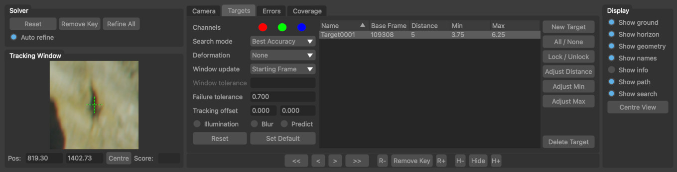
The Target Camera Solver node is an interactive camera tracking node that can be used to track problematic shots. Depending on the type of camera motion, a camera cam be tracked by as little as a single tracking point by "eye-balling" the approximate distance from the camera to a tracking point and using that information to solve for the camera motion from one frame to another.
Note: that the Target Camera Solver node cannot estimate camera focal length, so this value must be entered into the Clip Input node before tracking.
Targets are created upstream using the User Track node and they have a position in 3D space defined by a distance from the camera. Targets also have an uncertainty that defines how well known this distance is. The target position in 3D space will be adjusted within this range whilst estimating camera motion:
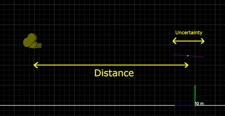
The range of distances that a tracker can have are displayed in the Viewer window as a purple line.
Usage
To use the Target Camera Solver, the following steps are recommended:
- Ensure the camera focal length is set correctly, and any lens distortion has been removed from the shot in the Clip Input node.
- Position one or more targets in the first frame of the clip and set approximate distances and uncertainty values for each tracker using the Initialise button.
- Use the tracking buttons in the Solver tools to solve the camera motion for a few frames and refine the camera position and tracker distances using the Refine All button.
- Introduce additional targets if required (making sure to initialise their distance) and continue tracking the camera forwards through the clip as needed.
As the camera is solved, the camera position will be estimated using the approximate target positions, and the distances of each target from the camera will be updated to best match the tracking points. When Auto refine is enabled, the entire camera path will be automatically refined after each camera solve.
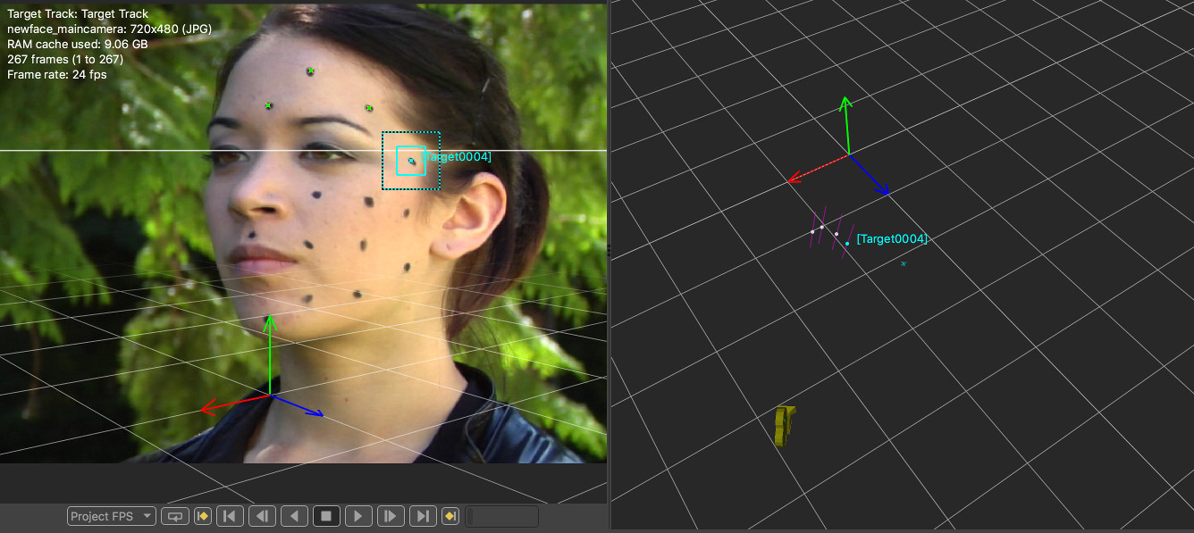
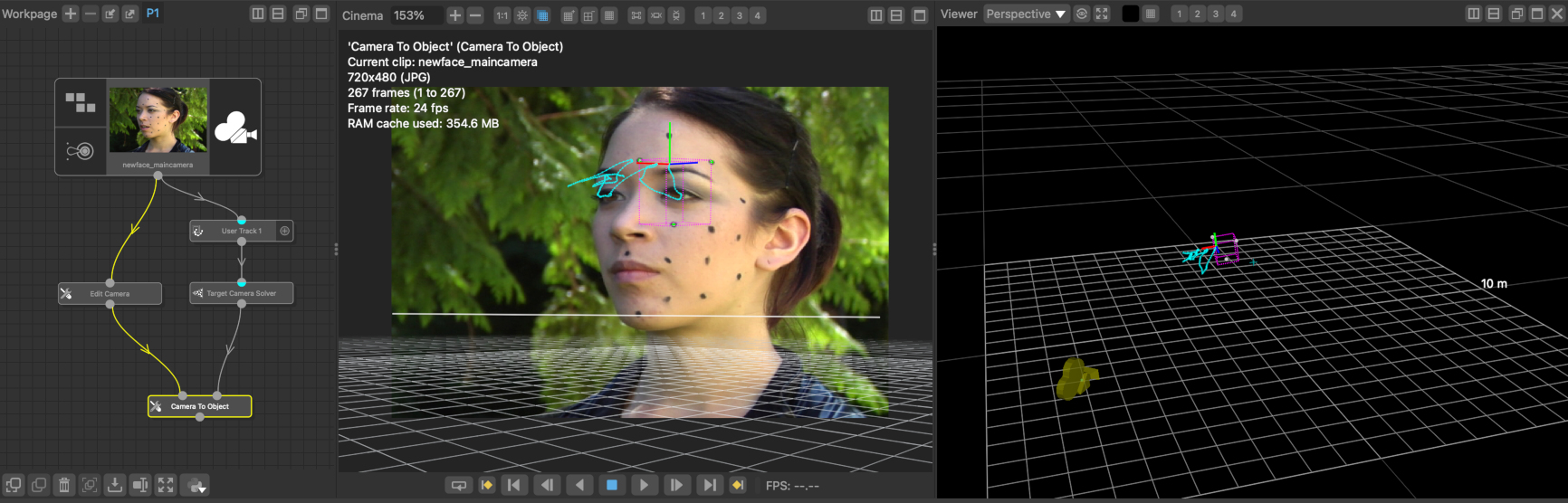
Here is an example of three targets positioned on a static object (footage from hollywoodcamerawork.com/trackingplates.html.
And here is the resulting camera path after the camera motion was solved from the first frame to the last frame of the clip:
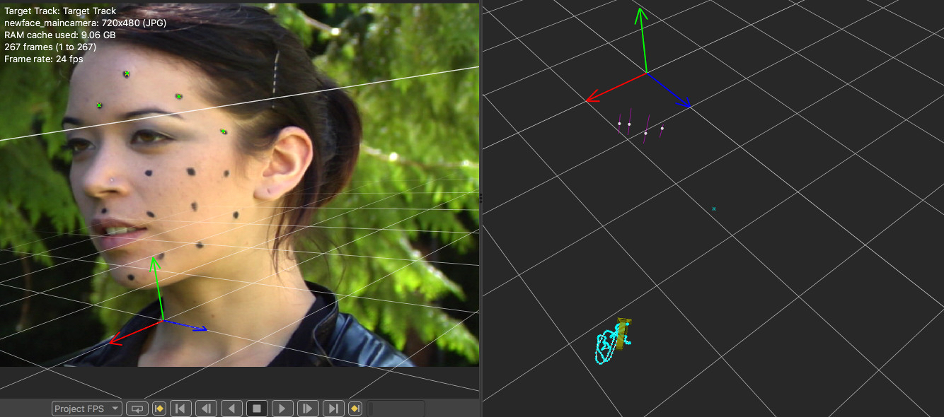
In this case, we really wanted the object to move and the camera to be fixed in place, so after the camera is solved satisfactorly, a Camera To Object node was used to convert the camera motion around a static object into object motion relative to the camera:
Controls
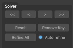
The Solver controls are used to track and solve the camera through the clip:
 : track the camera backwards by 5 frames.
 : track the camera backwards by 1 frame at a time.
 : track the camera forwards by 1 frame at a time.
 : track the camera forwards by 5 frames.
- Reset: Reset the solved camera path to its default state.
- Remove Key: Remove the current keyframe from the camera path.
- Refine All: Refine both the camera path and 3D target positions to better fit the target paths.
- Auto refine: When enabled, every adjustment to a target tracker will mean all target distances and camera positions are updated
Camera
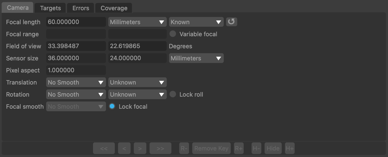
Focal length: The camera focal length at the current frame. Focal length can be set as Constant or Variable, and the focal length must be set before tracking.
Field of view: The horizontal and vertical field of view at the current frame, measured in Degrees.
Sensor size: The horizontal and vertical sensor/film back size. To change sensor size, edit the camera preset values in the Clip Input node.
Squeeze: The current lens squeeze ratio. To change the pixel aspect ratio, edit the camera preset value in the Clip Input node.
Translation: The type of camera translation and smoothing. Smoothing options are None, Low, Medium and High. Camera translation types are Free (a freely moving camera) or No Translation (for a camera that only rotates).
Rotation: The type of camera rotation and smoothing. Smoothing options are None, Low, Medium and High. Camera rotation types are Free (a freely rotating camera) and None (for a camera that only translates).
Lock roll: When enabled, the camera roll (i.e. rotation around the Z axis) will be locked.
Targets
![]()
The target list contains all targets that will be used for solving the camera. The Base Frame indicates the frame in which the target was initialised, and is used to define the 3D target position according to the Distance of the tracker from the camera in that frame, along with the Uncertainty.
The tracking group used for the targets can be selected from the Tracker Groups menu. Typically trackers from am upstream User Track node will be used.
All / None: Select all or none of the targets for tracking.
Activate: Activate the selected targets to use when solving the camera.
Deactivate: Deactivate the selected targets, preventing them from being used when solving the camera.
Initialise: Initialise the selected target to a default distance and uncertainty in the current frame.
Distance: Display a popup window allowing distances for all selected trackers to be set manually.
Uncertainty: Display a popup window allowing uncertainties for all selected trackers to be set manually.
Push/Pull: When enabled, clicking and dragging with the left mouse button in a 3D viewer window will change the distance of selected targets from the camera in their base frame. Hold Ctrl whilst dragging to adjust the uncertainty instead of the distance.
Residual Errors
![]()
The errors graph plots the residual error, measured in pixels (also called the reprojection Error) for each tracker in each frame, along with the average residual error for all trackers visible in a frame.
The resideual error is the difference between the tracker path position and the projection of the 3D tracker point onto the camera plane. Ideally, the residual error should be close to zero for each tracker.
Selected trackers are shown in yellow, and unselected trackers are shown in blue. The average residual error graph is shown in white. The error graph can be translated and scaled by clicking and dragging with the right or middle mouse buttons.
Individual trackers can be selected from the graph by clicking with the left mouse button. When a tracker is selected, the current frame will change to match the frame number that was clicked in the graph. If the Centre View display option is also enabled, the Cinema window will be panned to display the tracker location in the centre. Click and drag with the left mouse button to select multiple trackers at the same time.
All: When enabled, error graphs will be shown for all trackers, otherwise a graph will only be shown for selected trackers.
 : Clicking the Fit-to-area button and use the left mouse button to draw a rectangle in the residual error graph. When the button is released, the viewport will be fit as closely as possible to the selected area.
 : Clicking the Fit button will scale and translate the error graph so all graphs are visible.
Edit: When a single tracker is selected, click the Edit button to enable the Tracker Adjustment controls in the Cinema window.
Coverage
The Coverage Panel displays information about the frames in which each target has been tracked, along with other information such as the per-frame residual error for the camera solve:
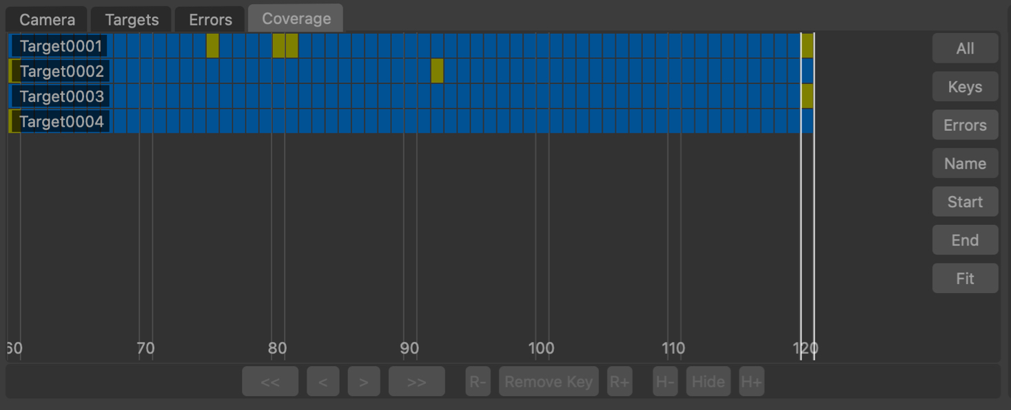
The Coverage Panel displays each target as a horizontal chart, illustrating the frames in which each target is visible. The current frame is displayed using white vertical lines.
By default, the Coverage Panel displayed keyframe information showing how targets have been positioned and tracked. Each frame in which the target is present is shown with a blue square. Yellow squares show frames in which the target was manually placed.
Frames in which the target is visible but has not been positioned are displayed in dark red. It is important to ensure that targets have been positioned in all frames in which they are visible.
Alternatively, the Coverage Panel can also display the residual error for each target point by clicking the Errors button. This switches the colour-coding of each indicator to show the error of the solved point in each frame. This is colour-coded to show green for less than 0.5 pixels error, yellow for 1.5 pixels error, and red is greater than 2.5 pixels.
Clicking on any indicator will select the target point and display that frame in the Cinema window. Holding the Ctrl key will allow multiple targets to be selected.
The panel can be panned horizontally or vertically by clicking and dragging with the right mouse button. Clicking and dragging with the middle mouse button will zoom either horizontally or vertically to increase the number of targets and frames that are displayed in the panel.
The mouse wheel can also be used to zoom horizontally, or vertically if the Alt/Option key is held.
All: Switch between displaying all trackers, or only those targets visible in the current frame.
Keys: Display keyframe information, showing where targets have been tracked and manually positioned.
Errors: Display residual error information.
Name: Sort the targets by name, in alphabetical order.
Start: Sort the targets according to the first frame in which they are tracked.
End: Sort the targets according to the last frame in which they are tracked.
Edit: When a single tracker is selected, click the Edit button to enable the Tracker Adjustment controls in the Cinema window.
: Click the Fit button to fit the targets display to the window. This will zoom in or out as necessary, displaying as many targets and frames as will fit in the viewport.
Tracker Adjustment
![]()
The tracker adjustment buttons appear in the Cinema window when a tracker is selected for editing by clicking an Edit button. The Cinema will zoom in to centre on a closeup of the tracking point.
The following buttons can be used to adjust the tracking point and quickly correct any errors locally whilst solving the camera:
![]() : Click the Re-Solve button to re-solve the tracker position.
: Click the Re-Solve button to re-solve the tracker position.
![]() : Click the In-point button to set the tracker in-point to the current frame.
: Click the In-point button to set the tracker in-point to the current frame.
![]() : Click the Track backwards button to track backwards by 5 frames, starting from the current frame..
: Click the Track backwards button to track backwards by 5 frames, starting from the current frame..
![]() : Click the Track backwards once button to track backwards by 1 frame, starting from the current frame.
: Click the Track backwards once button to track backwards by 1 frame, starting from the current frame.
![]() : Click Hide button to hide the tracker in the current frame, or click Show to re-show it.
: Click Hide button to hide the tracker in the current frame, or click Show to re-show it.
![]() : Click the Track forwards once button to track forwards by 1 frame, starting from the current frame.
: Click the Track forwards once button to track forwards by 1 frame, starting from the current frame.
![]() : Click the Track forwards button to track forwards by 5 frames, starting from the current frame.
: Click the Track forwards button to track forwards by 5 frames, starting from the current frame.
![]() : Click the Out-point button to set the tracker out-point to the current frame.
: Click the Out-point button to set the tracker out-point to the current frame.
![]() : Click the Reset button to reset all tracker adjustments, reverting the tracker back to the original state passed into the node.
: Click the Reset button to reset all tracker adjustments, reverting the tracker back to the original state passed into the node.
Note: Adjustments made to trackers using these tools are local to the Target Camera Solver node, and do not affect the tracker position as defined by the original node that generated it. Adjustments to the original tracking point must be made in an upstream User Track node.
Nudge keyboard shortcuts
Holding down the Alt/Option modifier key while pressing the Left Right Up Down cursor key can be used to nudge the tracker position 1 pixel each key press (the nudge amount and keyboard shortcuts can be changed in the preferences).
Additional keyboard shortcuts are available to provide finer-grain adjustments (Ctrl + Alt/Option) modifier keys by default). This reduces the adjustment to 0.25 pixels, and this scale factor or keyboard shortcuts can be changed in the preferences).
Display
Cinema Ground Plane: When enabled, the ground plane will be displayed in the Cinema window.
Viewer Ground Plane: When enabled, the ground plane will be displayed in the Viewer windows.
Horizon Line: When enabled, the horizon line will be displayed in the Cinema window.
Geometry: When enabled, the geometric objects from up-stream will be displayed.
Tracker Names: When enabled, selected target names will be displayed.
Tracker Info: When enabled, selected target positional information will be displayed.
Tracker Paths: When enabled, target tracker paths will be displayed.
Centre View: When enabled, the image displayed in the Cinema window will be translated so that the first selected target is positioned in the centre of the window.
Default Keyboard Shortcuts
Default keyboard shortcuts are listed in the Keyboard and mouse section.