| Studio / Enterprise | #PFTrack Documentation | Node Reference |
Photo Survey
Overview | Point detection and matching | Using regions to help point matching | Solving for camera pose and 3D point cloud |Lens distortion correction | Using the photo solver | Camera information | Point adjustment | Creating new matches |
Solve refinement | Automatic matching controls | Photo Solver Controls | Match results | Matched points display |
Camera and Point Cloud display
Note: this node is part of the Photogrammetry toolset available with Studio or Enterprise editions
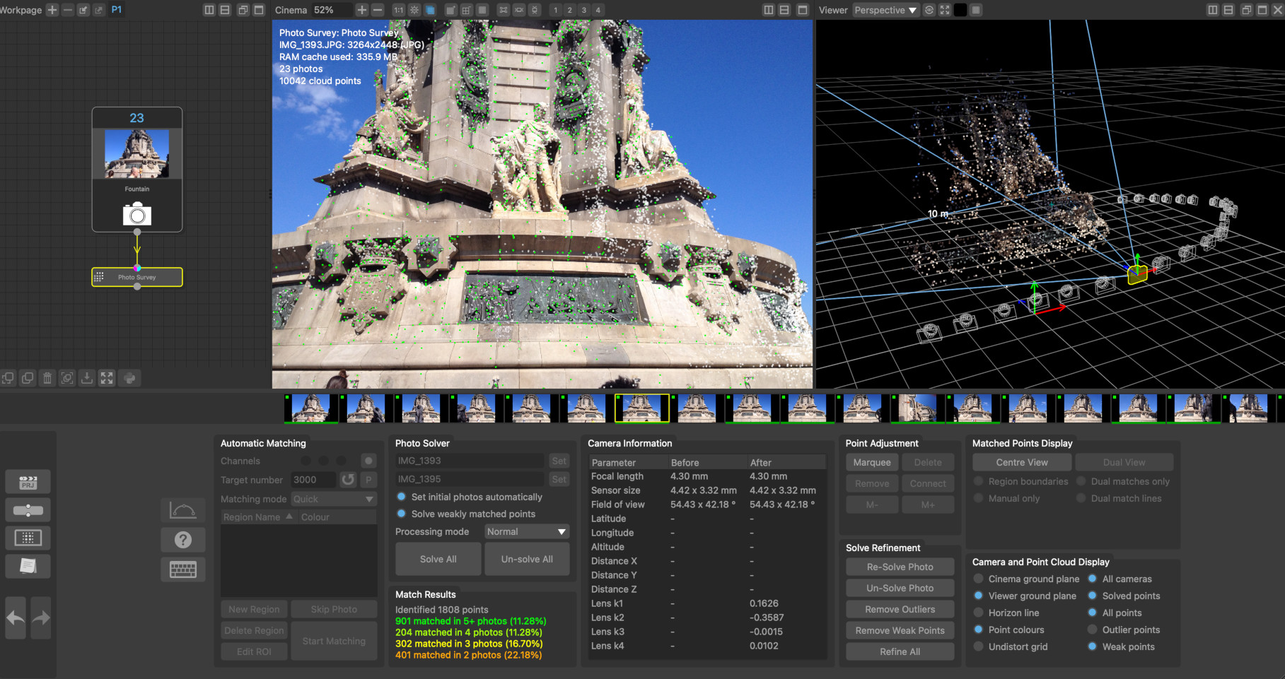
The Photo Survey node can be used to automatically identify and match features between a set of still photos, automatically estimate the position of each camera, and construct a sparse point cloud representing the 3D feature positions.
The set of photos that the Photo Survey node will process are generally provided by the Photo Input node and must have embedded EXIF metadata describing the camera model and focal length. Alternativewly, the Select Frames node can be used to convert a movie clip into a set of photos, provided the focal length of your camera is known.
Once the camera positions and sparse point cloud have been constructed, the overall scale and orientation of the scene can be set using an Orient Camera node.
Additional moving cameras can be tracked into the same scene using the Match Camera node. The point cloud and camera positions can also be exported using the Scene Export node.
Finally, the Photo Cloud and Photo Mesh nodes can also be used to construct a dense point cloud and textured triangular mesh.
Overview
The process of reconstructing a set of camera positions and a sparse point cloud is split into several stages, each of which is described in further detail below:
1. Point detection in each photo
2. Point matching between pairs of photos
3. Camera pose estimation and 3D point cloud construction
Generally, a large number of photos should be captured, covering the entire scene to be reconstructed from multiple positions and angles.
Photos should be taken from different camera positions. There must also be a significant amount of overlap between each photo to help with point matching. For example, when capturing photos around the outside of a building it would be advisable to take a step or two between each shot whilst pointing the camera at the building.
PFTrack separates the process of detecting and matching points from that of solving for the camera positions and 3D point cloud, so the matching process generally only needs to be performed once for each scene before solving for the camera positions. Additional manual point matches can then be added if required, and the 3D camera positions and point cloud re-solved after each edit to ensure an accurate scene is reconstructed.
The overall quality of the solution is strongly affected by the number of points that are picked and matched between photos. There must be enough points distributed over each photo area to ensure an accurate estimate of the camera position can be made, but including too many poorly located points (for example, by reducing the Pick threshold to a very low value) may reduce the overall accuracy.
The number of points picked in each photo also affects the overall time required to match the points and solve for the camera positions.
Point detection and matching
The Matching Mode menu in the Automatic Matching panel can be used to select an appropriate mode for matching points between photos. The default option here is Quick which will attempt to identify the most similar looking photos and match points between them. The Slower matching mode will attempt to identify more similar photos for matching. This may improve results will comes at the cost of increased processing speed.
Changing this to Exhaustive will match every photo to every other photo. This will greatly increase the time required to match all photos, but can sometimes provide more accurate results if the Quick matching mode is unable to select the best candidate photos.
If GPS position and orientation metadata is available (for example, captured by an airborne drone), this can be used to accelerate the matching process by using the From Metadata matching mode.
Using regions to help point matching
Regions can be specified in multiple photos to assist with point matching. A region constrains the locations to which a point can be matched in other photos. When a region is placed in a photo, every point that falls inside it can only be matched to another point inside the region in other photos. This can be helpful when using photos of a scene that contains large amounts of similar visual structure.
For example, the front and left sides of a building may contain many identical windows, and without any other constraints, points picked on the front of the building may be incorrectly matched to points on the side of the building in other photos. Whilst the solver is robust to a certain amount of incorrect matches, large numbers of them can affect the solution and cause the solver to fail.
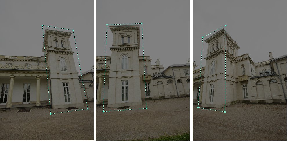
By creating a region for the front of the building and drawing that region in every photo where it is visible, any point picked on the front will be prevented from matching a point on the side of the building.
The following image shows a region covering one part of a building that has been placed in three different photos.
Solving for camera pose and 3D point cloud
Once points have been detected and matched between photos, the 3D camera positions and point cloud can be constructed.
Whilst EXIF metadata is used to initilise the camera focal lengths, it is important to recognize when this data may not always be entirely accurate. For example, many cameras only report the EXIF focal length metadata to the nearest whole number (i.e. 35mm). The actual focal length mat be slightly different from the reported value.
Lens distortion correction
In order to get the most accurate estimate of camera positions and 3D point cloud, it is important to account for any lens distortion present in the photos. This can be done in several ways:
- Shooting calibration grids and building a distortion preset using the Photo Camera Preset editor.
- Using automatic distortion correction that is enabled in the Photo Input node. This is the default approach to removing lens distortion.
After lens distortion has been removed, the camera's sensor size will be adjusted to account for the new image resolution.
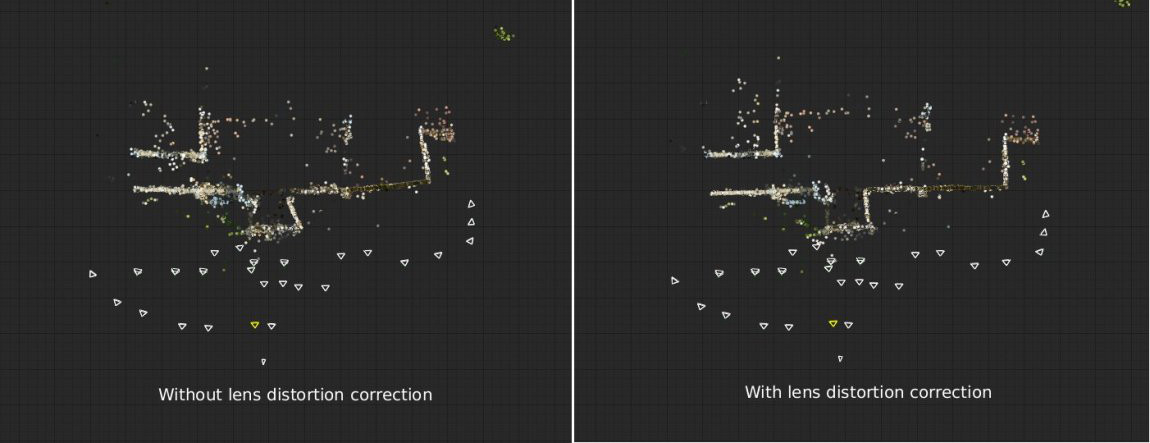
The image below shows camera positions and point cloud reconstructed from a set of photos with and without lens distortion correction. When lens distortion is ignored, errors in the position of wall structures can clearly be seen when viewed from above.
Using the photo solver
Estimates of camera pose are initialised using a pair of photos, Initial Photo A and Initial Photo B. These photos will be estimated automatically when the Set initial photos automatically option is enabled.
Note that the choice of initial photos can have a significant impact on the quality of the final 3D point cloud, or whether all photos can be solved together. It is important that there is a significant distance between the camera positions for photo A and photo B, and that there are enough points matched between the photos.
PFTrack will attempt to find the most optimal pair of photos to use, but in some situations, initial photos can be identified that are not able to provide an accurate solution (this is especially true when there are a large number of badly matched points present in those photos).
If initial photos are not being estimated automatically, they can be set manually by clicking the Set button next to each photo name to set it to the photo currently visible in the Cinema window.
Once the solve has finished, points can be adjusted or created using the tools in the Point Adjustment panel, and the solution refined to account for any changes using the tools in the Solve Refinement panel.
Generally, the 3D position of most points in the cloud can be estimated accurately. These are shown as green dots in the Cinema window when the Solved points display option is enabled. Some points cannot be reconstructed accurately, however, and these so-called Outliers will be shown in red provided the Outlier points display option is enabled, along with a line connecting the 3D point position with the 2D point position that was detected in the photo.
Note: the more outliers exist in the set of point matches, the harder it is to reconstruct the camera positions and 3D point cloud. This is particularly true for architectural scenes that contain repeated horizontal structure such as windows. In these cases it can become difficult to distinguish one window from another and therefore care must be taken to ensure that the majority of point matches are correct in situations such as this. This is especially the case when the position from which the photos are taken lies in a plane parallel to these repeated structures (for example, taking all photos of the windows from exactly head height whilst walking in a straight line along the ground) because incorrect matches between different windows can still be triangulated accurately even though they should not form part of the final point cloud
Camera Information
The Camera Information panel show useful information for before and after the camera positios have been solved. This includes the camera focal length and sensor size, the horizontal and vertical field of view, and the 35 mm equivalent focal length for the current photo.
If GPS location data is available in your photo, this will also be displayed, along with the distance between the original GPS location and the solved camera position, measured in meters.
When lens distortion is being corrected automatically, the lens distortion coefficients will be also be displayed here for reference.
Point adjustment
Points can be selected in either the Cinema or Viewer windows by clicking the Marquee button in the Point Adjustment controls and then clicking and dragging with the left mouse button to draw a selection rectangle. Alternatively, if the Shift key is held, a selection lasso will be drawn. Holding the Ctrl key will allow multiple selections to be made. Selected points are coloured purple. Clicking the Delete button will delete all selected points. Single points can also be selected when the Marquee button is not enabled by clicking with the left mouse button.
The photos containng the selected points will be displayed in the scrub-bar as purple indicators on the photo thumbnail. The M- and M+ buttons can be used to quickly move between the photos where the point has been matched. If required, the Centre View display option can be enabled to centre the Cinema view on a point in each photo.
Clicking the Remove button will allow point matches to be removed from the current photo. Moving the moue over a point will highlight it in light-blue, and clicking the left mouse button will remove the point match from the current photo. This can be used to remove incorrectly matched points when the photo solver is failing to estimate camera pose correctly.
Creating new matches
To create new matches, the the Cinema view can be split by clicking the Reference View button in the Matched Points Display. This will take the current photo and display it in the right-half of the Cinema window. The photo displayed in the left-half of the window can then be adjusted as usual using the frame controls (or cursor keys).
When Reference View is enabled (and, if the point cloud has already been solved and the Solved points display option is switched off to show the original matches), the Connect button can be clicked allowing new points to be created and matched between the two photos in the reference view.
Clicking the left mouse button will create a connecting line, allowing a point in the other photo to be matched by clicking again with the left mouse button.
You can toggle display of the match lines using the Reference match lines display option, or hide all points that haven't been manually matched by enabling the Manual only display option.
Solve refinement
The solve refinement controls can be used to adjust or refine the camera positions and point cloud after any adjustments have been made to the points. These tools can also be used to clean up and poorly solved points or outliers before refining, which can often improve the overall quality of the solution.
Clicking the Remove Outliers button will remove all outlying points in the current photo. Holding the Shift key whist clicking the button will remove outliers from all photos at the same time.
Clicking the Remove Weak Points button will remove all weakly solved points in the current photo. A weakly solved point that is one that is only matched accurately in two photos. Holding the Shift key whist clicking the button will remove weakly solved points from all photos at the same time.
The Refine All button can then be used to refine the overall camera positions and 3D point cloud positions to better fit the remaining feature matches.
Clicking the Un-solve Photo button will remove the current photo from the camera solution. The Re-Solve photo will solve it again using point matches in the current frame. Again, the Refine button can be used afterwards to improve the overall solution.
Automatic matching controls
Channels: Select which of the red, green or blue channels will be used for point matching, and a mask controls to adjust how masks are used.
Target Number: The target number of points that will be picked from each photo. The default value is 2000.
P: Display a preview of points picked in the current photo in the Cinema window.
Matching mode: This controls how points are matched between photo. Options are Quick for fast maching, Slower for slower but more accurate matching, Exhaustive where one photo will be matched against all other photos, and From Metadata will use EXIF position and orientation information to accelerate the matching process.
3Skip Photo: Skip (or un-skip) the current photo when detecting and matching points.
Edit ROI: Allow the region of interest (ROI) for point detection to be adjusted in the Cinema window. Click and drag with the left mouse button to adjust edges of the ROI.
New Region: Create a new matching region.
To draw the region in the current image, make sure it is selected in the regions list and then click with the left mouse button in the Cinema window to place vertices around the area of the image you wish to constrain. Drawing can be aborted at any time by pressing the Escape key, and the region must be closed by clicking again on the first vertex. Once a region has been drawn in one image, you must also draw it in all other images that view the same part of the scene. To remove a region from the current image, double click with the left mouse button in the Cinema window.
Delete Region: Delete the currently selected matching region.
Start Matching: Start the point detection and matching process. If the Shift key is held whilst clicking this button, the process will be performed in the background.
Photo solver controls
Set initial photos automatically. When enabled, the initial photos used to start the solve will be estimated automatically. When disabled, the Set buttons can be used to set these manually.
Solve weakly matched points. When enabled, points that have only been matched in two photos will be included in the solution. This will increase the number of points in the point cloud, but some of these points may not be solved as accurately as others.
Solve All: Start the camera solve process. If the Shift key is held whilst clicking this button, the process will be performed in the background.
Un-solve All: Reset the camera solve and clear the 3D point cloud positions.
Match results
The match results panel shows how many points are matched in the current photo. This includes matches to multiple other photos which can be used as an indicator of how much coverage your photo dataset has for your scene.
Matched points display
Centre View: When enabled, the Cinema window will be panned so the selected point is at the centre.
Reference View: Split the Cinema window down the middle, keeping the current photo on the right-hand side. Navigating to another photo will update the left-hand side of the split, allowing points to be manually matched between two different photos.
Region boundaries: When this option is enabled, region matching boundaries will be displayed in the Cinema window.
Reference matches only: When enabled, only those points that have been matched between the left and right-hand photos in the reference view will be displayed.
Manual matches only: When enabled, only those points that have been matched manually using the Connect button will be displayed. This option is only available when the Show solved points option is switched off and the Cinema window is split.
Camera and Point Cloud Display
Cinema ground plane: When this option is enabled, the ground plane will be displayed in the Cinema windows.
Viewer ground plane: When this option is enabled, the ground plane will be displayed in the Viewer windows.
Horizon line: When this option is enabled, the horizon line will be displayed in the Cinema windows.
Point cloud colours: When this option is enabled, points displayed in the Viewer windows will be coloured using the pixel colour from the corresponding location in the source photos. When disabled, the points will be coloured green, red or white according to their inlier status.
Undistort grid: When this option is enabled, the distortion grid will be displayed as an overlay in the Cinema window (this option is only available when automatic lens distortion correction is enabled.
All cameras: When this option is enabled, all camera positions will be displayed in the Viewer windows.
Solved points: When this option is enabled, solved 3D point positions will be displayed in the Cinema window.
All cloud points: When this option is enabled, all cloud points will be displayed in the Cinema and Viewer windows. When this option is disabled, only those points that have been matched in the current photo will be displayed.
Weak points: When enabled, weakly solved points will be displayed in the Cinema and Viewer windows.
Default Keyboard Shortcuts
Default keyboard shortcuts are listed in the Keyboard and mouse section.